
Industrial Automation and Control Unit 5 Notes explain how compressed air produces and controls industrial motion. The unit, Pneumatics in Automation, connects gas laws, pressure, flow and moisture control with compressors, air dryers, receivers, FRL service units, cylinders and directional valves.
These notes are for AKTU B.Tech 5th Semester EE and EN students studying BEE053. Labelled diagrams, operating sequences, comparison tables and worked numerical examples explain the complete path from atmospheric air intake to actuator movement.
Topics Covered
| Topic | Topic |
|---|---|
| 5.1 Introduction to pneumatics | 5.15 Service unit: FRL |
| 5.2 Role in industrial automation | 5.16 Filter and regulator operation |
| 5.3 Pressure, temperature and air flow | 5.17 Single-acting actuators |
| 5.4 Boyle’s law | 5.18 Double-acting actuators |
| 5.5 Charles’s law and combined gas law | 5.19 Cylinder force and bore selection |
| 5.6 Scientific context of the laws | 5.20 Speed, stroke time and air use |
| 5.7 Bernoulli equation | 5.21 Directional-valve notation |
| 5.8 Absolute and relative humidity | 5.22 Two-port, two-position valves |
| 5.9 Atmospheric and pressure dew point | 5.23 Three-port, two-position valves |
| 5.10 Complete pneumatic system | 5.24 Single-acting actuator circuit |
| 5.11 Compressor construction and working | 5.25 Double-acting control with two 3/2 valves |
| 5.12 Aftercooler and moisture separation | 5.26 Valve–actuator problems and faults |
| 5.13 Air dryers | 5.27 Worked automation station |
| 5.14 Air tank or receiver | 5.28 Revision and examination practice |
5.1 Introduction to Pneumatics
Pneumatics uses compressed gas, usually air, to transmit and control power. An electric motor drives a compressor, prepared air passes through pipes and valves, and an actuator converts pressure energy into useful motion.
A pneumatic cylinder produces linear movement. Air leaving its working chamber normally exhausts to atmosphere. The piston moves when the net pressure force exceeds the opposing load, friction and any return-spring force.
Pressure establishes force potential; delivered air flow largely determines attainable speed.
Power, Control and Feedback
| Path | Main elements | Function |
|---|---|---|
| Power | Compressor, treatment equipment, receiver, pipes, valve and actuator | Produce, prepare, route and use compressed air |
| Control | Pushbutton, mechanical roller, pneumatic pilot or electrical solenoid | Change valve state |
| Feedback | Position sensors and PLC inputs | Confirm actuator or process condition |
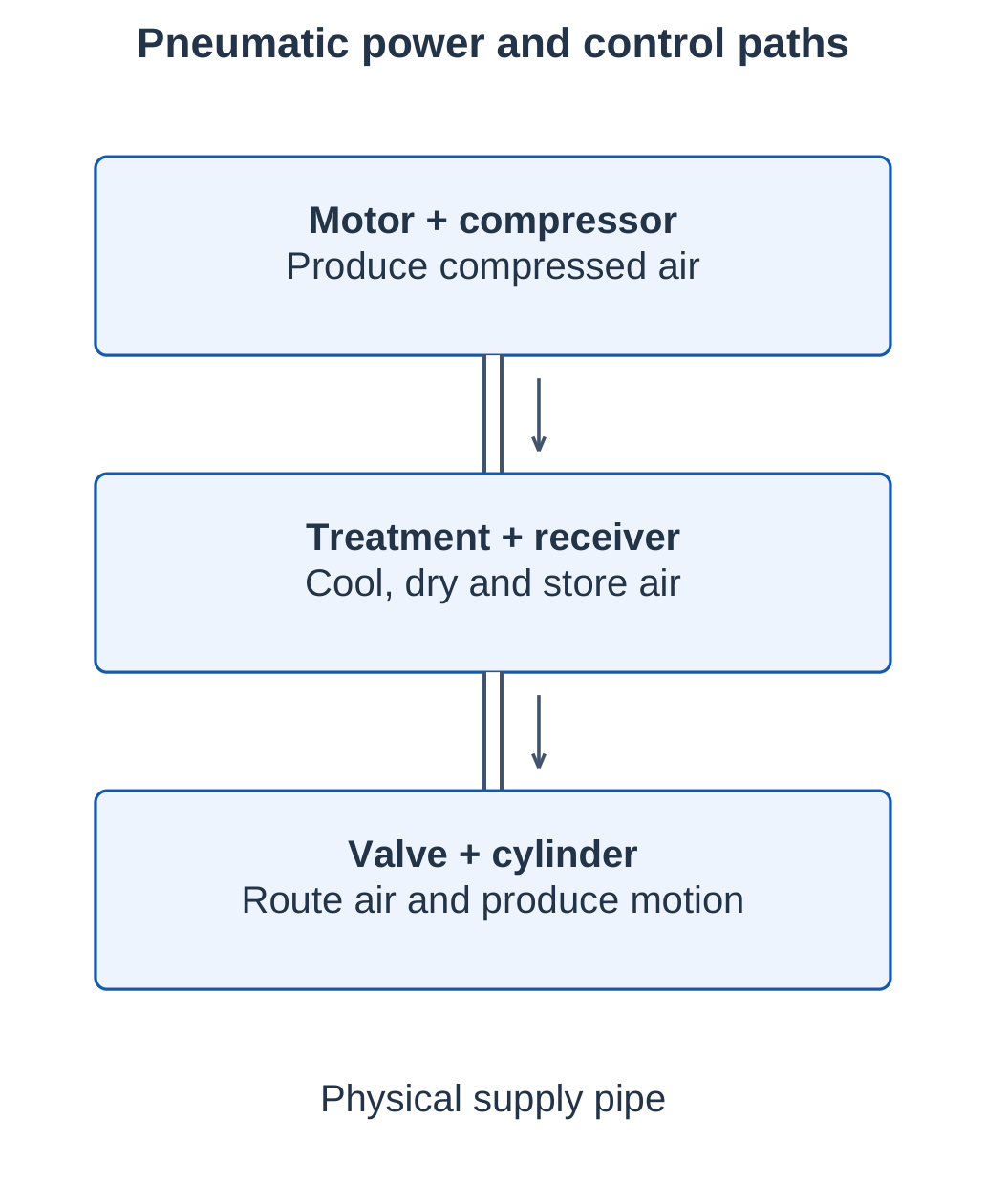
An equipment sketch shows physical construction and connections. A circuit symbol represents function; it need not resemble the actual valve body.
To predict movement, trace supply to the working chamber and exhaust from the chamber that must empty. A blocked exhaust can stop movement even when supply pressure is available.
5.2 Role in Industrial Automation
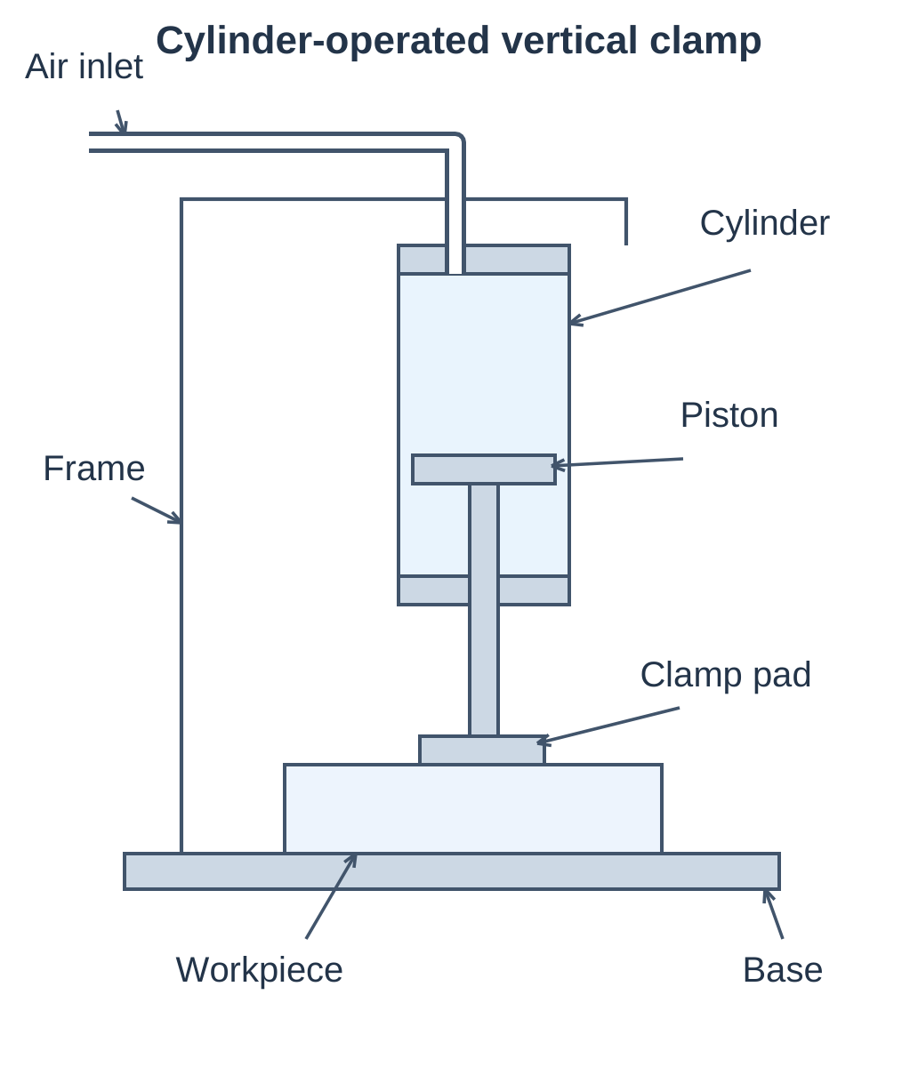
Pneumatics is used for repeated movements such as clamping, pushing, sorting, gripping and positioning. Cylinders can be installed close to the task while a valve bank centralises their control.
| Industry or station | Application | Main consideration |
|---|---|---|
| Packaging | Carton pusher and stopper | Stroke time and impact |
| Assembly | Part clamping and insertion | Force and alignment |
| Material handling | Diverter and gripper | Detection and grip |
| Machine tools | Fixture actuation | Holding requirement |
| Process equipment | Valve actuation | Defined loss-of-air state |
Advantages
- Readily available working medium.
- Rapid cycling with simple actuators.
- Convenient integration with solenoid and PLC control.
- Local exhaust without a hydraulic liquid-return circuit.
- Compact equipment for short repetitive strokes.
Limitations
- Air compressibility causes compliance and load-dependent motion.
- Precise positioning requires suitable feedback and design.
- Compression consumes electrical energy.
- Leaks continuously waste compressed air.
- Noise, particles, condensate and lubrication requirements need attention.
Pneumatic and Hydraulic Comparison
| Feature | Pneumatic system | Hydraulic system |
|---|---|---|
| Medium | Compressible air | Low-compressibility liquid |
| Typical behaviour | Fast, compliant motion | Stiffer, high-force motion |
| Outlet path | Usually atmosphere | Usually tank return |
| Practical concern | Air quality and leakage | Fluid condition and leakage |
5.3 Pressure, Temperature and Air Flow
Pressure is normal force per unit area:
p = F / A
The SI unit is the pascal: 1 Pa = 1 N/m².
| Conversion | Value |
|---|---|
| 1 bar | 100 kPa |
| 1 MPa | 10 bar |
| 1 L | 0.001 m³ |
Gauge and Absolute Pressure
Gauge pressure is measured above local atmospheric pressure. Absolute pressure is measured from vacuum.
p(abs) = p(gauge) + p(atmosphere)
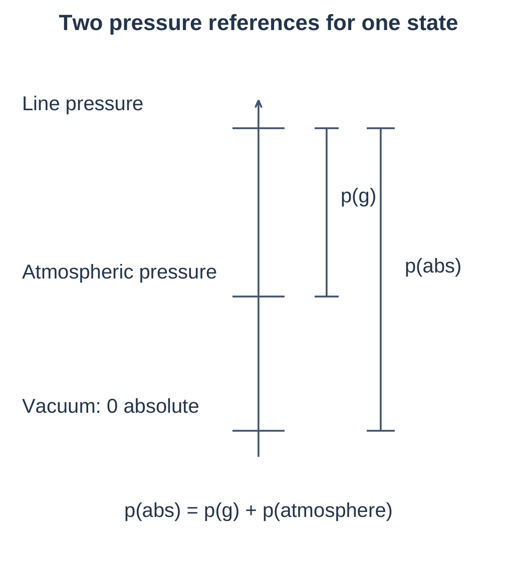
If line pressure is 6 bar gauge and atmosphere is approximated as 1 bar, line pressure is 7 bar absolute. Use the atmospheric value supplied in a problem; 1 bar is a classroom approximation.
Temperature
Gas-law temperatures must be in kelvin:
T(K) = t(°C) + 273.15
A Celsius temperature ratio is invalid. Heating from 20°C to 40°C does not double absolute temperature.
Flow Vocabulary
| Quantity | Meaning |
|---|---|
| Actual volumetric flow | Volume per time at specified line conditions |
| Mass flow | Air mass per time |
| Reference or free-air flow | Equivalent volume rate at defined reference conditions |
The same air mass occupies a smaller volume at higher absolute pressure. Therefore, actual L/min and reference L/min cannot be interchanged directly.
Use absolute pressure for gas laws and air-consumption conversions. Cylinder force against atmospheric exhaust commonly uses gauge pressure, with opposing pressure and friction treated consistently.
5.4 Boyle’s Law
For a fixed mass of ideal gas at constant temperature, absolute pressure varies inversely with volume:
p₁V₁ = p₂V₂
Thus pV = constant and p ∝ 1/V.
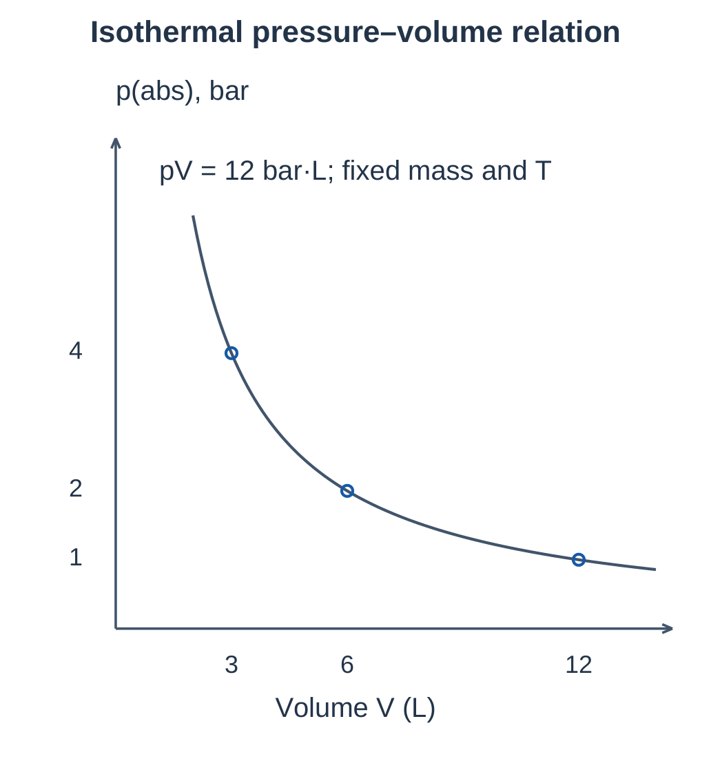
Slow, well-cooled compression approximates the isothermal relation better than rapid hot compression.
Worked Example: Compression
Air occupies 12 L at 1 bar absolute and is compressed isothermally to 3 L.
p₂ = p₁V₁ / V₂ = 1 × 12 / 3 = 4 bar absolute
With atmosphere approximated as 1 bar:
Final gauge pressure = 4 − 1 = 3 bar gauge
Worked Example: Expansion
Air initially occupies 2 L at 6 bar gauge. Atmosphere is 1 bar. It expands isothermally to 7 L without losing mass.
- Initial absolute pressure = 6 + 1 = 7 bar.
- Final absolute pressure = 7 × 2 / 7 = 2 bar.
- Final gauge pressure = 2 − 1 = 1 bar.
A cylinder filling through an open supply valve is an open system. Identify the fixed gas mass and states before applying the trapped-gas equation.
5.5 Charles’s Law and Combined Gas Law
Charles’s Law
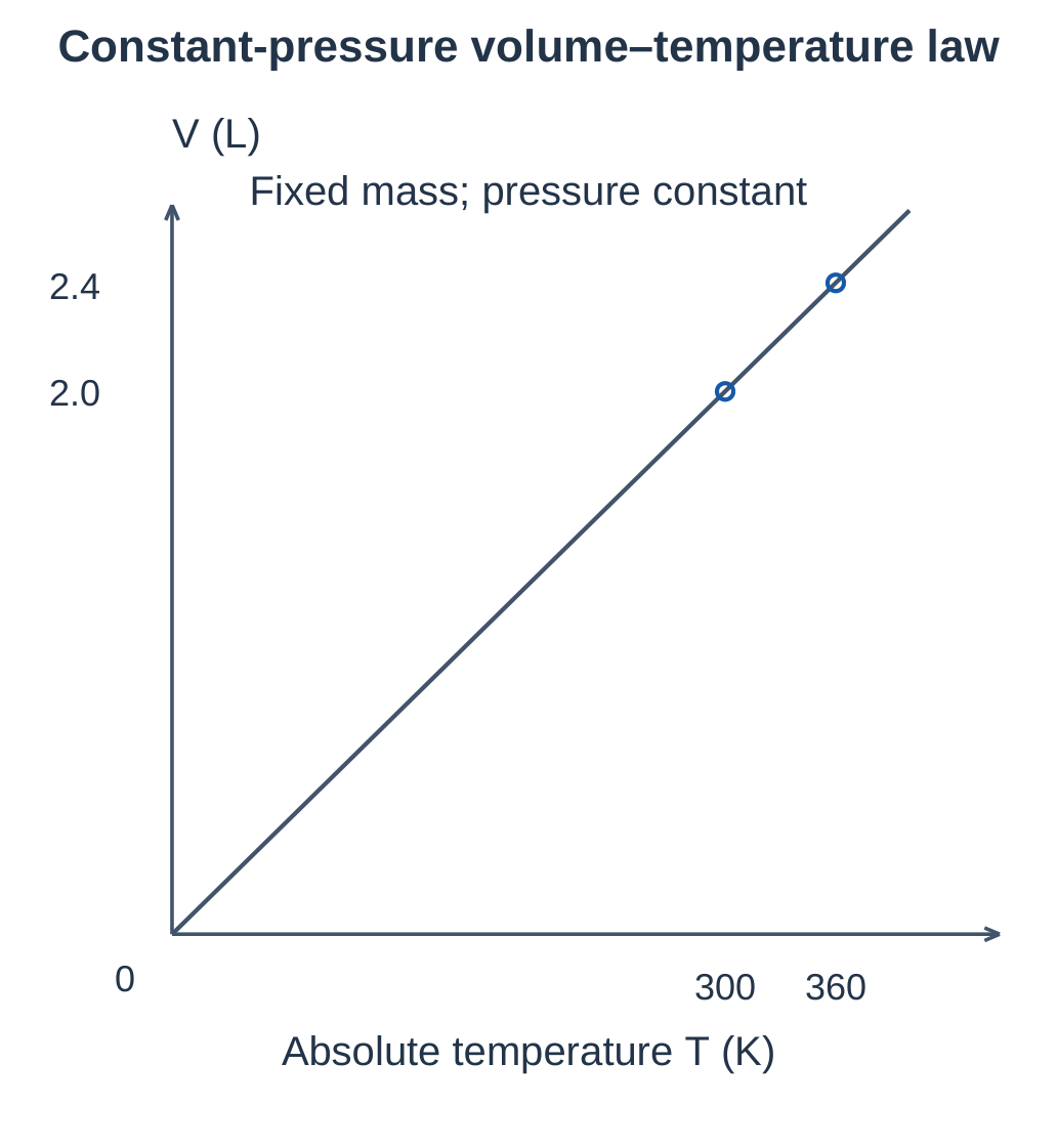
For a fixed mass at constant absolute pressure, ideal-gas volume is proportional to absolute temperature:
V₁ / T₁ = V₂ / T₂
A volume–temperature graph using kelvin is a straight line through the ideal origin. The extrapolation does not mean real air stays gaseous at every temperature.
Worked Example: Heating
A movable piston contains 2 L of air at 27°C. Pressure remains constant while temperature reaches 87°C.
- T₁ = 27 + 273.15 = 300.15 K.
- T₂ = 87 + 273.15 = 360.15 K.
- V₂ = 2 × 360.15 / 300.15 ≈ 2.40 L.
- Volume increase ≈ 0.40 L.
Combined Gas Law
For fixed mass:
p₁V₁ / T₁ = p₂V₂ / T₂
This follows from pV = mRT when gas mass and gas constant remain unchanged.
In a sealed rigid vessel, volume is constant. If pressure is 5 bar absolute at 300 K and temperature rises to 330 K:
p₂ = 5 × 330 / 300 = 5.5 bar absolute
This is a constant-volume pressure–temperature relation.
| Law | Held constant | Relation |
|---|---|---|
| Boyle | Mass and temperature | pV = constant |
| Charles | Mass and pressure | V/T = constant |
| Combined | Mass | pV/T = constant |
5.6 Scientific Context of the Laws
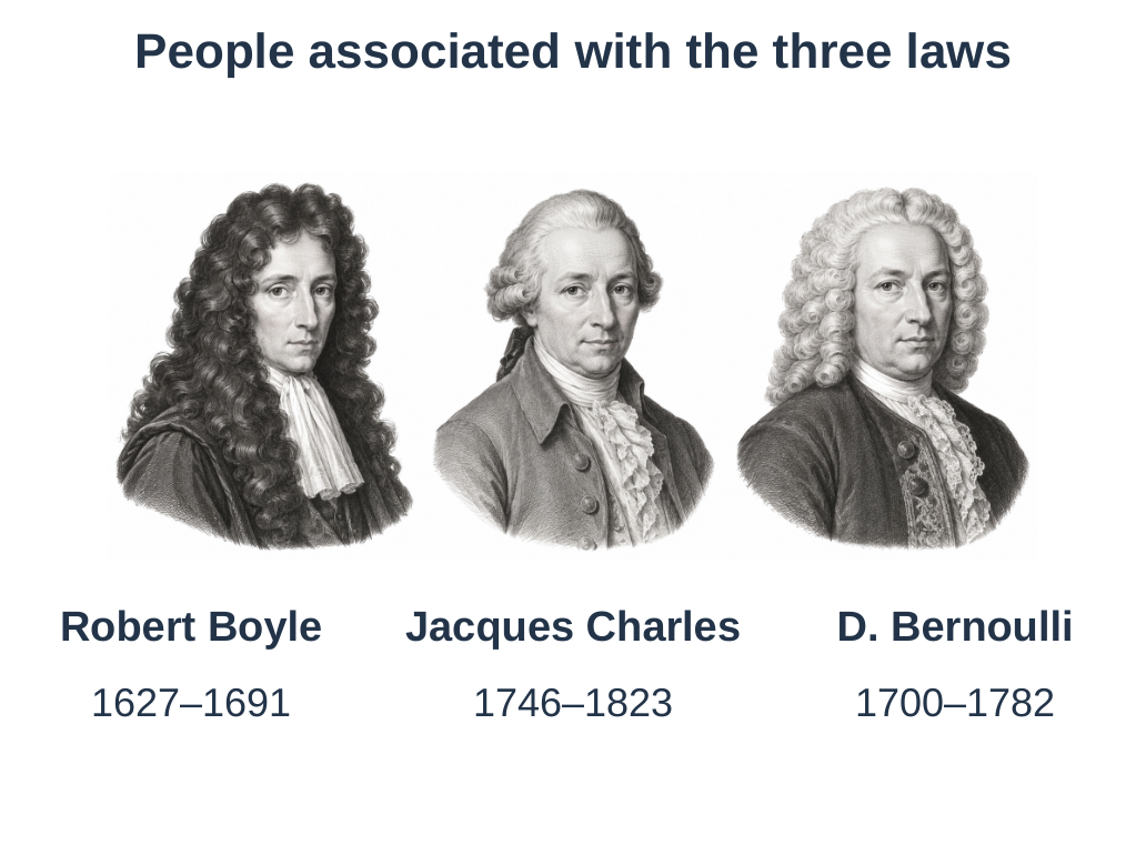
| Scientist | Associated relationship | Application |
|---|---|---|
| Robert Boyle | Pressure inversely related to volume at fixed temperature | Ideal isothermal compression and expansion |
| Jacques Charles | Volume proportional to absolute temperature at fixed pressure | Heating or cooling gas with a movable boundary |
| Daniel Bernoulli | Pressure, velocity and elevation in ideal fluid flow | Reasoning about restrictions under suitable assumptions |
Remember each formula with its conditions:
- Gas-law pressures are absolute.
- Gas-law temperatures are in kelvin.
- The elementary Bernoulli form assumes approximately constant density.
5.7 Bernoulli Equation
For steady, inviscid, incompressible flow along a streamline, with no added shaft work:
p + ½ρv² + ρgz = constant
| Symbol | Meaning |
|---|---|
| p | Static pressure |
| ρ | Fluid density |
| v | Flow speed |
| g | Gravitational acceleration |
| z | Elevation |
All three terms have pressure units.
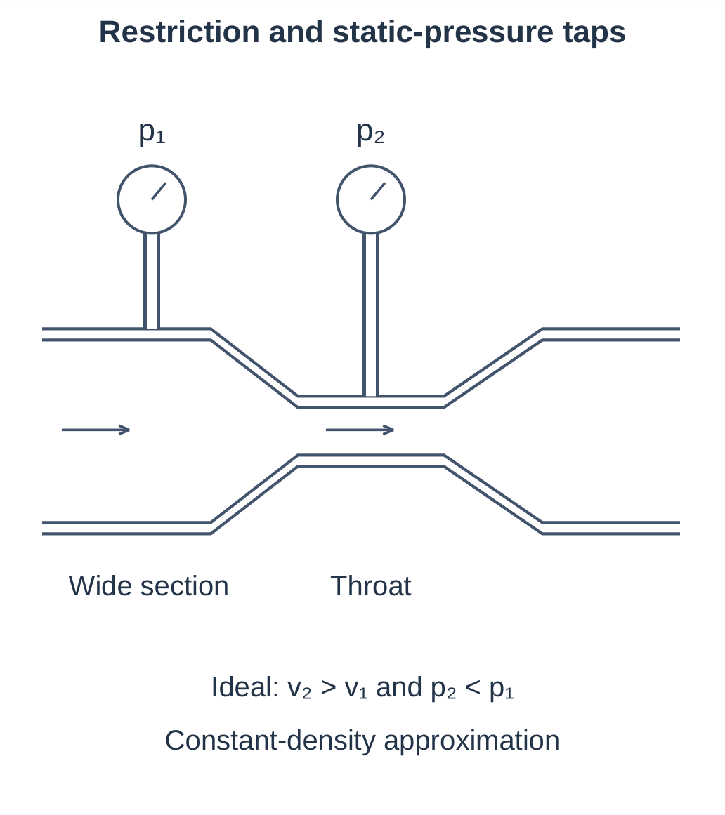
At equal elevation:
p₁ + ½ρv₁² = p₂ + ½ρv₂²
For incompressible continuity:
A₁v₁ = A₂v₂
A smaller area raises speed. The ideal model predicts lower static pressure in the throat; real restrictions have losses and incomplete pressure recovery.
Worked Example
Assume air density is constant at 1.2 kg/m³. Speed rises from 10 to 30 m/s at equal elevation.
Pressure decrease = ½ × 1.2 × (30² − 10²) = 480 Pa
This is a static-pressure difference.
Limits in Pneumatics
The principle helps explain restrictions and lubricator oil pickup. Large compressed-air pressure changes require compressible-flow treatment and appropriate equipment data. The elementary incompressible expression cannot give an exact exhaust speed from a high-pressure supply.
5.8 Absolute and Relative Humidity
Atmospheric air already contains water vapour. Compression does not create water; it changes pressure, temperature and vapour concentration per actual volume. Cooling can convert vapour into liquid condensate.
Absolute Humidity
Absolute humidity is water-vapour mass per unit actual air volume:
ρᵥ = mᵥ / V
Units are g/m³ or kg/m³. Specify the air conditions associated with the volume.
If 0.024 kg of vapour occupies 3 m³:
ρᵥ = 0.024 / 3 = 0.008 kg/m³ = 8 g/m³
Relative Humidity
Relative humidity compares actual vapour partial pressure with saturation vapour pressure at the same temperature:
RH = 100 × pᵥ / pₛₐₜ(T)
At saturation, RH is 100%.
If pᵥ = 1.5 kPa and pₛₐₜ = 3.0 kPa:
RH = 100 × 1.5 / 3 = 50%
If saturation pressure later becomes 2.0 kPa while pᵥ stays 1.5 kPa:
RH = 75%
| Feature | Absolute humidity | Relative humidity |
|---|---|---|
| Definition | Vapour mass / actual volume | Actual / saturation vapour pressure |
| Unit | g/m³ or kg/m³ | Percent |
| Temperature role | Air volume and state must be specified | Saturation reference changes with temperature |
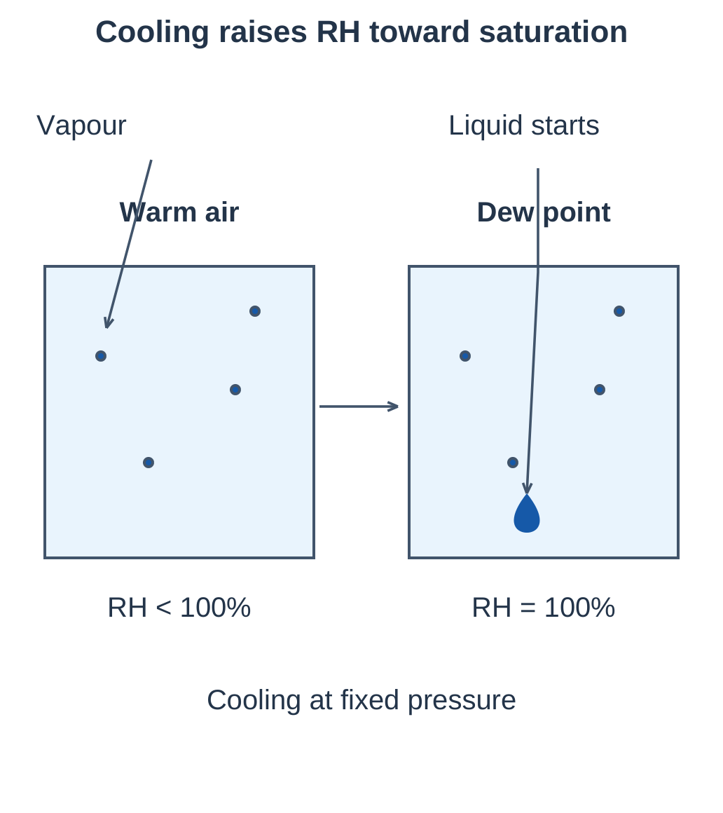
Heating without adding water generally lowers RH. Cooling without removing vapour raises RH until condensation begins.
5.9 Dew Point: ADP and PDP
Dew point is the temperature at which water vapour becomes saturated during cooling at a specified pressure. Further cooling can form liquid water or ice under the relevant conditions.
| Feature | Atmospheric dew point: ADP | Pressure dew point: PDP |
|---|---|---|
| Pressure reference | Approximately atmospheric pressure | Stated compressed-air pressure |
| Interpretation | Moisture state at atmospheric conditions | Condensation risk inside a pressurised line |
| Conversion requirement | Vapour relation and pressure | Vapour relation and pressure |
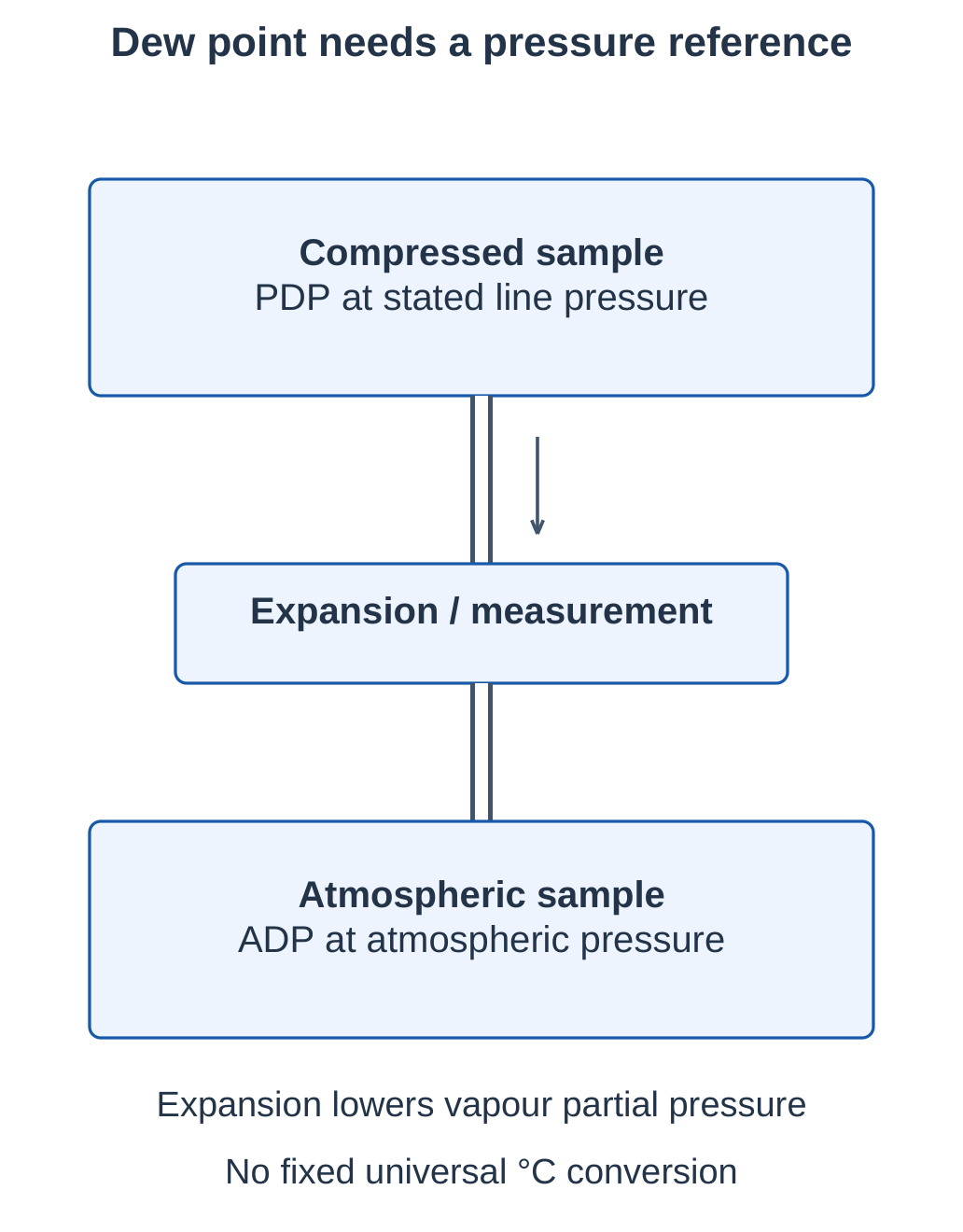
For the same vapour mole fraction, increasing total pressure raises vapour partial pressure and generally raises dew point. Expansion to atmospheric pressure generally lowers the corresponding dew point.
Condensation Example
Dryer outlet PDP is +3°C at operating pressure.
- A downstream line at +15°C is above PDP; cooling to that temperature alone is not expected to condense water vapour.
- Temperature margin = 15 − 3 = 12°C.
- A line section at −2°C is below PDP and can collect moisture or ice.
Reheating lowers RH but does not itself remove more water or lower PDP at unchanged pressure.
5.10 Complete Pneumatic System
A typical air path is:
Intake filter → Compressor → Aftercooler → Separator and drain → Receiver → Dryer → Distribution → FR(L) → Directional valve → Actuator
Exact receiver and dryer placement depends on plant design.
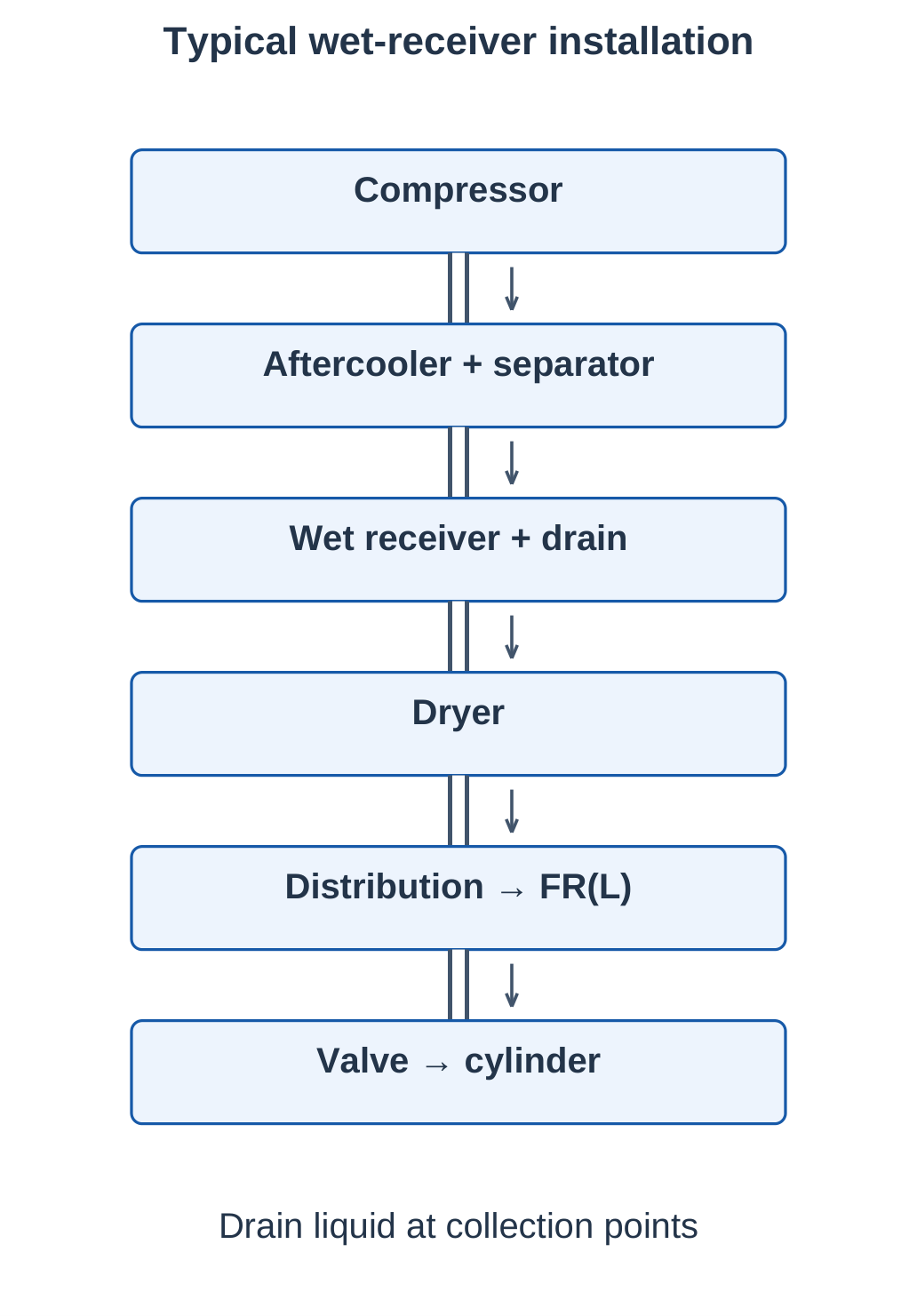
| Stage | Main job | Limitation |
|---|---|---|
| Compressor | Raise pressure | Does not ensure dry, clean air |
| Aftercooler | Remove compression heat | Does not guarantee low dew point |
| Separator and drain | Remove liquid condensate | Do not remove all vapour |
| Receiver | Store air and buffer demand | Storage is finite |
| Dryer | Lower water-vapour content | Does not regulate working pressure |
| FRL or FR | Prepare local supply | Does not replace all central treatment |
| Valve and actuator | Control and produce motion | Position feedback needs sensors |
Wet and Dry Receivers
- Wet receiver: Upstream of the dryer; can collect additional condensate.
- Dry receiver: Downstream of the dryer; stores treated air.
Both require suitable pressure-rated fittings and appropriate condensate and pressure controls.
Parallel outlines in equipment sketches show physical pipes. Single lines in circuit drawings show functional pneumatic connections.
5.11 Compressor: Construction and Working
A compressor draws atmospheric air and delivers it at higher pressure. A reciprocating compressor uses a crank-driven piston inside a cylinder.
Operating Sequence
Step 1: Suction. The piston increases cylinder volume, reducing pressure below intake pressure. The inlet valve opens while the discharge valve stays closed.
Step 2: Compression. The inlet closes and decreasing cylinder volume raises pressure.
Step 3: Delivery. The discharge valve opens when cylinder pressure sufficiently exceeds delivery-side pressure.
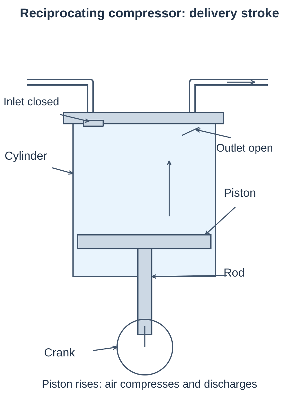
Compression raises temperature. Downstream cooling, separation and drying prepare the air for use.
| Feature | Reciprocating compressor | Rotary screw compressor |
|---|---|---|
| Compression element | Piston and cylinder | Meshing helical rotors |
| Delivery | Pulsating before buffering | Relatively continuous |
| Common duty | Intermittent or selected industrial duty | Continuous plant duty |
| Maintenance focus | Valves, rings and mechanism | Rotor system and specified oil/filtration |
Pressure and Capacity
Pressure rating and flow capacity are different. Delivered flow must cover simultaneous consumption, leakage and suitable reserve. Check whether capacity is quoted as free-air delivery or actual compressed volume rate.
5.12 Aftercooler and Moisture Separation
An aftercooler removes heat from compressed air. As air cools, some water vapour condenses. A separator collects the liquid and a drain removes it.
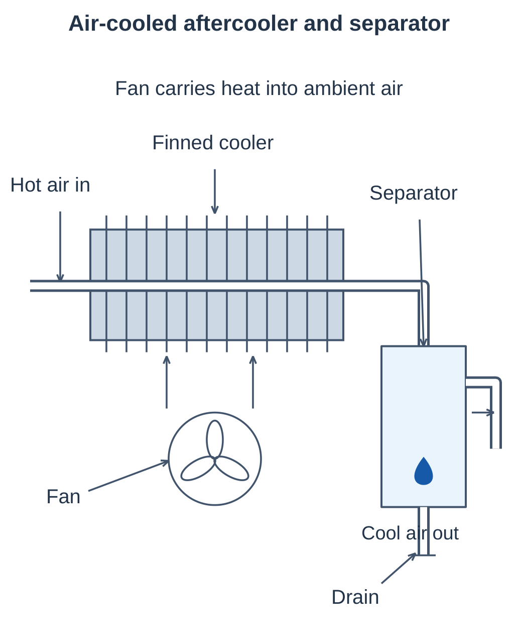
| Feature | Air-cooled aftercooler | Water-cooled aftercooler |
|---|---|---|
| Cooling medium | Ambient air, often fan-driven | Cooling water |
| Heat path | Air passage → fins → ambient | Air passage → exchanger wall → water |
| Important condition | Ambient temperature and airflow | Water temperature and flow |
| Fluid separation | Compressed air separate from cooling air | Compressed air separate from water |
Cooling water is not intentionally mixed into the compressed air. Liquid drops in sketches represent condensate, not invisible vapour.
Why an Aftercooler Is Not a Dryer
An aftercooler permits bulk liquid separation but normally leaves vapour. If downstream air falls below its remaining PDP, more condensation can occur. A dryer meets the required dew-point condition.
For excessive outlet temperature, inspect cooling surfaces, fan operation or cooling-water flow. For liquid carryover despite adequate cooling, inspect the condensate drain.
5.13 Air Dryers
An air dryer reduces water-vapour content to meet a specified dew point. Selection depends on pressure, inlet temperature, flow and required PDP.
Refrigerated Dryer
- Cool compressed air.
- Condense water vapour.
- Separate and drain liquid.
- Reheat the outlet where the design uses heat recovery.
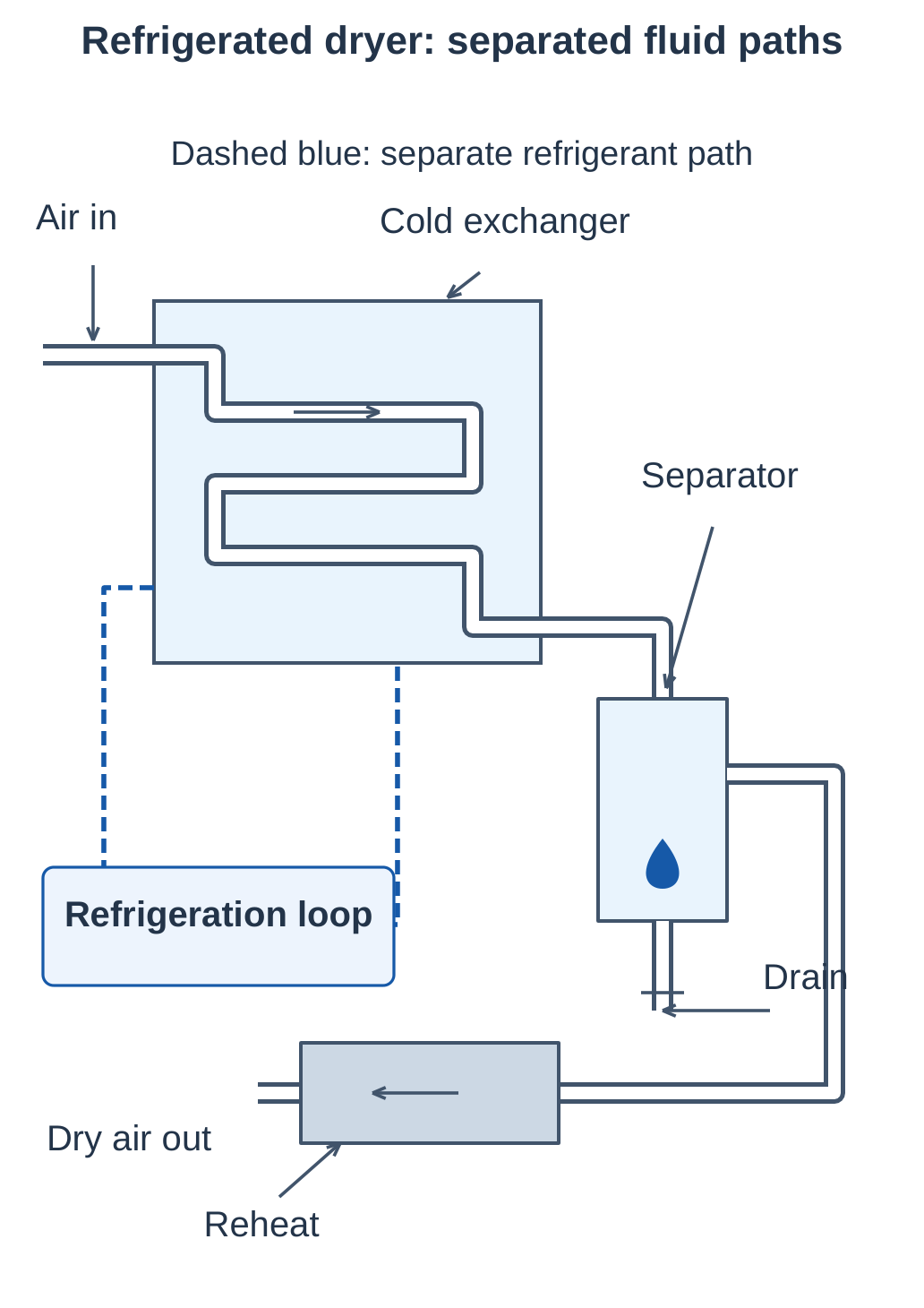
The moisture removal occurs during cold separation. Reheating lowers outlet RH.
Desiccant Dryer
Desiccant adsorbs water vapour onto its surface. Twin-tower designs alternate a drying bed with a regenerating bed. Regeneration can use purge air, heat or a combined method.
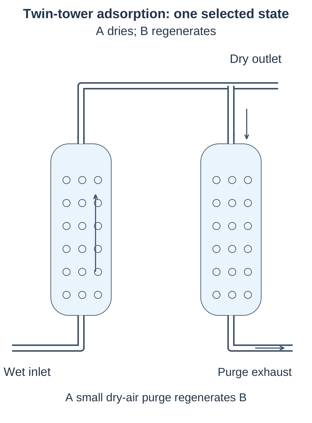
| Feature | Refrigerated dryer | Desiccant dryer |
|---|---|---|
| Method | Cooling, condensation and separation | Vapour adsorption |
| Usual duty | General plant air above freezing | Lower-dew-point applications |
| Requirement | Refrigeration and working drain | Bed regeneration and protection |
| Possible fault | Poor cooling or drain failure | Saturated bed or failed regeneration |
Choose PDP below the lowest downstream temperature with an appropriate margin. Filtration removes relevant particles or aerosols; it does not remove all water vapour.
5.14 Air Tank or Receiver
A receiver is a pressure-rated air-storage vessel. It smooths compressor pulsations, buffers short demand peaks and provides pressure monitoring and liquid drainage.
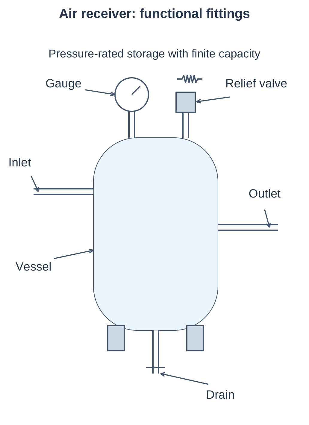
| Fitting | Function |
|---|---|
| Pressure gauge | Indicate vessel pressure |
| Relief valve | Limit excessive pressure according to its design and setting |
| Drain | Remove collected liquid |
| Pressure switch or controller | Request compressor start, stop or unloading |
| Check arrangement | Prevent unwanted reverse flow where required |
A relief valve is not the normal actuator pressure regulator. A receiver cannot correct a sustained compressor-capacity shortfall.
Air-Release Estimate
At approximately constant temperature, with equal receiver and reference temperatures:
Vref = Vr × (p₁ − p₂) / pref
Use absolute pressures.
For a 100 L receiver falling from 8 to 6 bar absolute, with pref = 1 bar:
Vref = 100 × (8 − 6) / 1 = 200 L
At 100 reference L/min demand, this corresponds ideally to 2 minutes without compressor contribution. Remaining pressure must still meet actuator requirements. Temperature changes and delivery losses affect the practical result.
5.15 Service Unit: FRL
FRL = Filter + Regulator + Lubricator
Normal series order is F → R → L, when lubrication is required. Prelubricated equipment may use an FR arrangement without added oil.
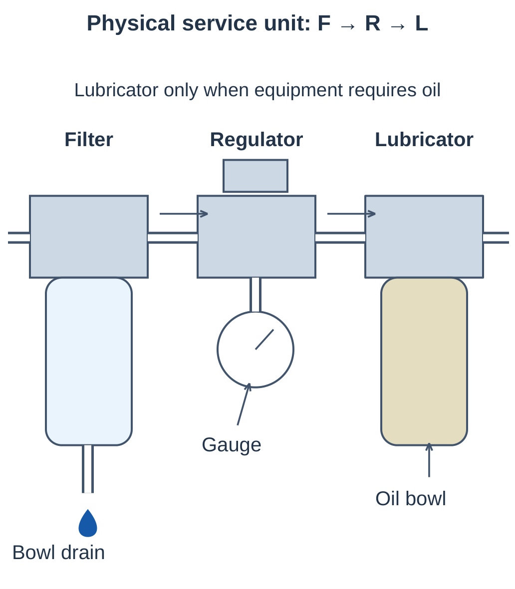
| Component | Function | Inspection or adjustment |
|---|---|---|
| Filter | Remove specified particles and collected liquid | Element, bowl and drain |
| Regulator | Maintain selected downstream pressure within operating limits | Setting and downstream pressure |
| Lubricator | Meter oil mist for compatible equipment | Correct oil and metering |
The filter does not replace vapour drying. A regulator cannot raise outlet pressure above inlet supply. Lubricator use must match equipment requirements.
Assess pressure under relevant flow. A satisfactory static reading does not prove adequate cylinder pressure during a rapid stroke.
5.16 Filter and Regulator Operation
Filter Flow Path
- Air enters the separating and filtering region.
- The element removes particles according to its rating.
- Collected liquid settles in the bowl.
- The drain removes accumulated liquid.
- Air leaves through the outlet.
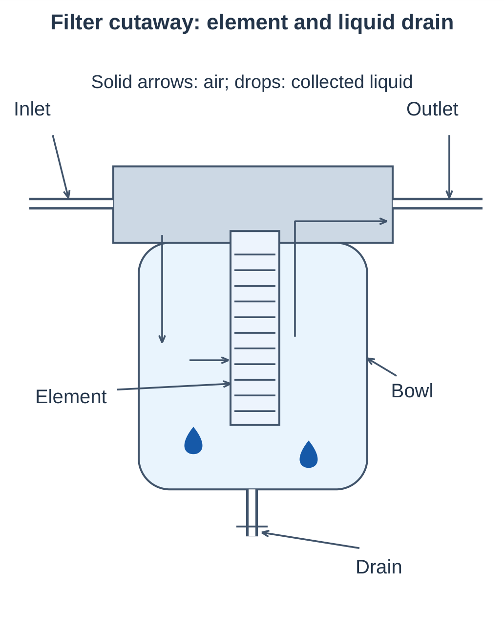
Observe the marked flow direction.
Regulator Feedback
A spring setting acts through a diaphragm and valve mechanism. Downstream pressure opposes the spring.
- When outlet pressure falls during demand, the supply passage opens further.
- When outlet pressure rises, the passage throttles toward closure.
- Increasing spring setting tends to increase regulated pressure.
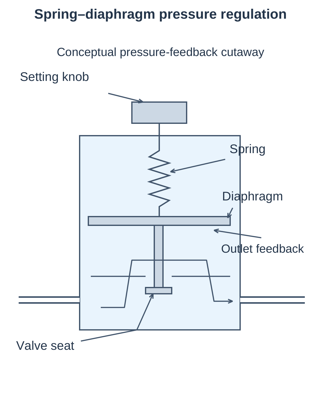
A relieving regulator can discharge excess downstream pressure through its designated relief path. A non-relieving regulator needs another way to reduce trapped downstream pressure.
Pressure Loss and Regulation
Pressure loss in pipework or a clogged filter reduces usable supply, especially during flow. Regulation deliberately controls outlet pressure. If inlet pressure becomes inadequate, the regulator cannot maintain its setting.
5.17 Single-Acting Actuators
A single-acting cylinder has one pressure-driven working direction. A spring or external force provides return.
In the illustrated spring-return arrangement, cap-end pressure extends the rod and exhaust permits spring retraction.
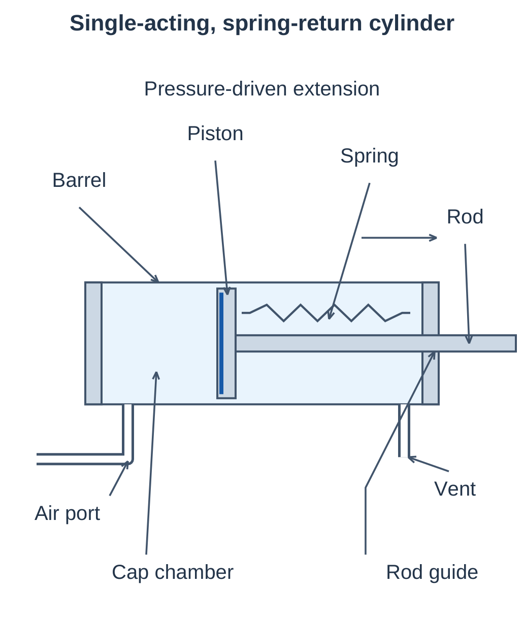
Construction
- Cylinder barrel and end covers.
- Sealed piston and piston rod.
- Rod guide and seal.
- Working air port.
- Return spring.
- Appropriate vent on the spring side.
Operation and Force
The piston moves when pressure force exceeds spring force, friction and load. The working chamber must exhaust before free spring return.
With the opposite side at atmosphere:
Available extension force ≈ pgA − Fs − Ff
| Symbol | Meaning |
|---|---|
| pg | Chamber gauge pressure |
| A | Effective piston area |
| Fs | Opposing spring force |
| Ff | Friction force |
Applications include small ejectors, light clamps and stop pins. Some arrangements are spring-extended and pressure-retracted; state the powered direction explicitly.
5.18 Double-Acting Actuators
A double-acting cylinder uses air pressure for extension and retraction. A single-rod cylinder has full piston area at the cap end and smaller annular area at the rod end.
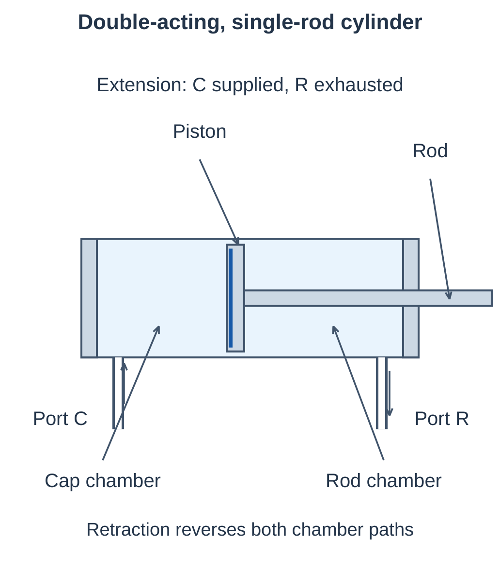
| Movement | Supplied chamber | Exhausted chamber |
|---|---|---|
| Extension | Cap end | Rod end |
| Retraction | Rod end | Cap end |
Single-Acting and Double-Acting Comparison
| Feature | Single acting, spring return | Double acting, single rod |
|---|---|---|
| Working air ports | One | Two |
| Powered directions | One | Both |
| Return | Spring or external force | Opposite-chamber pressure |
| Common control | 3/2 valve | 5/2 or 4/2 valve, or coordinated 3/2 pair |
| Force | Reduced by opposing spring where applicable | Depends on effective areas and opposing pressure |
Align the load and rod travel. Use suitable guides for side loads. Cushioning reduces end impact but does not replace correct speed and load selection.
Air compressibility and leakage mean blocked ports do not guarantee rigid, indefinite position holding.
5.19 Cylinder Force and Bore Selection
For bore diameter D and rod diameter d:
Full piston area: Ap = πD² / 4
Rod-side annular area: Aa = π(D² − d²) / 4
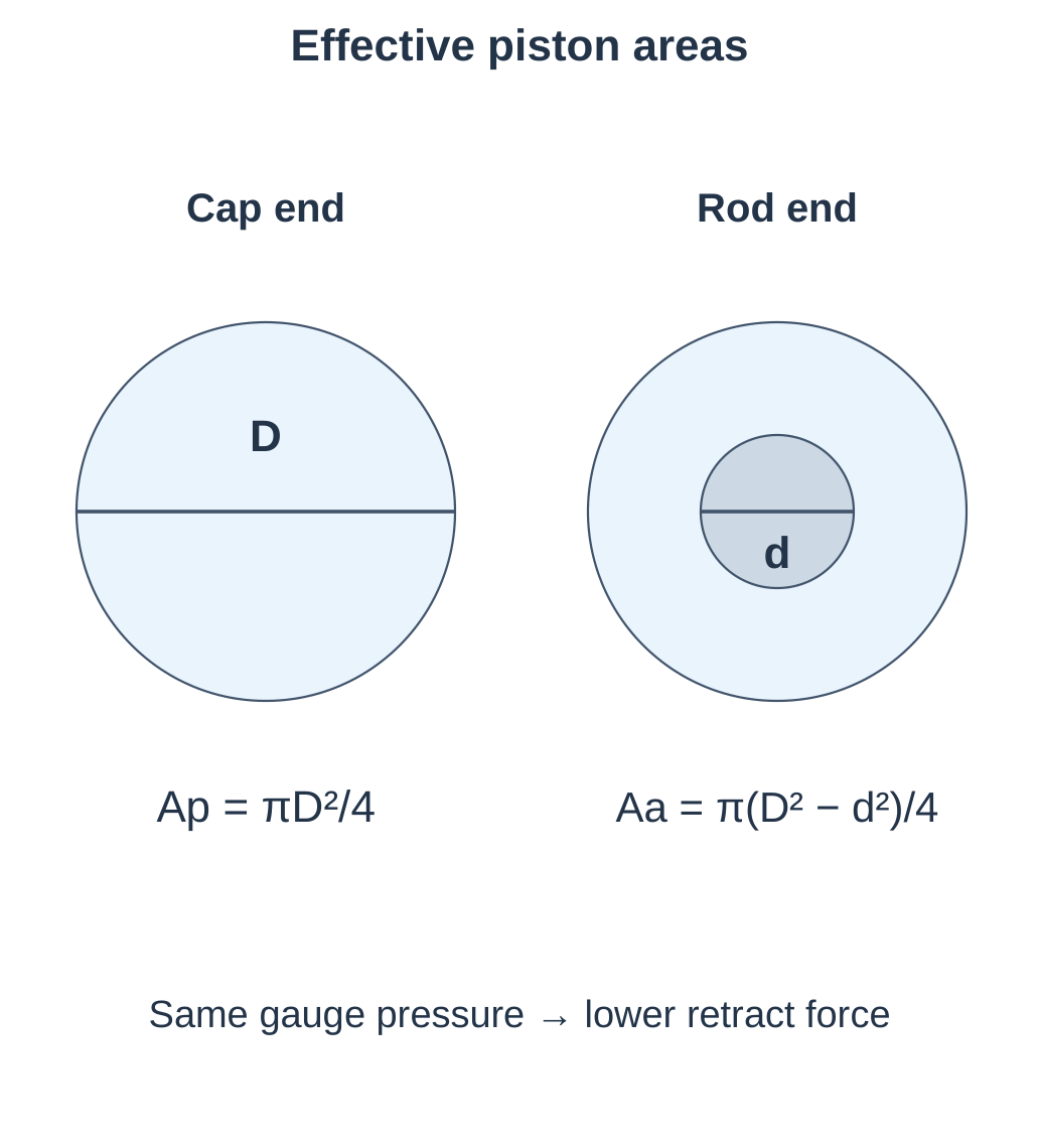
With the opposite chamber at atmospheric exhaust:
- Ideal extension force = pgAp.
- Ideal retraction force = pgAa.
Worked Double-Acting Example
D = 40 mm, d = 16 mm and pg = 6 bar = 600,000 Pa.
| Quantity | Result |
|---|---|
| Ap | 0.0012566 m² |
| Aa | 0.0010556 m² |
| Ideal extension | Approximately 754 N |
| Ideal retraction | Approximately 633 N |
Retraction force is lower because the rod reduces effective area.
Opposing Chamber Pressure
For extension:
Net pressure force = pcAp − prAa
For the same cylinder with cap pressure 6 bar gauge and rod pressure 1 bar gauge:
Net pressure force ≈ 754 − 106 = 648 N, before friction and external load.
Bore Estimate
Required ideal push = 500 N at 5 bar gauge:
A = 500 / 500,000 = 0.001 m²
D = √(4A/π) ≈ 35.7 mm
This is an ideal minimum. Select a suitable standard bore after allowing for friction, opposing pressure and force margin.
5.20 Speed, Stroke Time and Air Use
For actual chamber flow Q and effective area A at approximately constant chamber conditions:
v ≈ Q / A
t ≈ L / v
where L is stroke length.
Speed Example
A = 0.001 m² and Q = 12 actual L/min.
- Q = 12 × 0.001 / 60 = 0.0002 m³/s.
- v = 0.0002 / 0.001 = 0.2 m/s.
- For L = 0.1 m, t = 0.1 / 0.2 = 0.5 s.
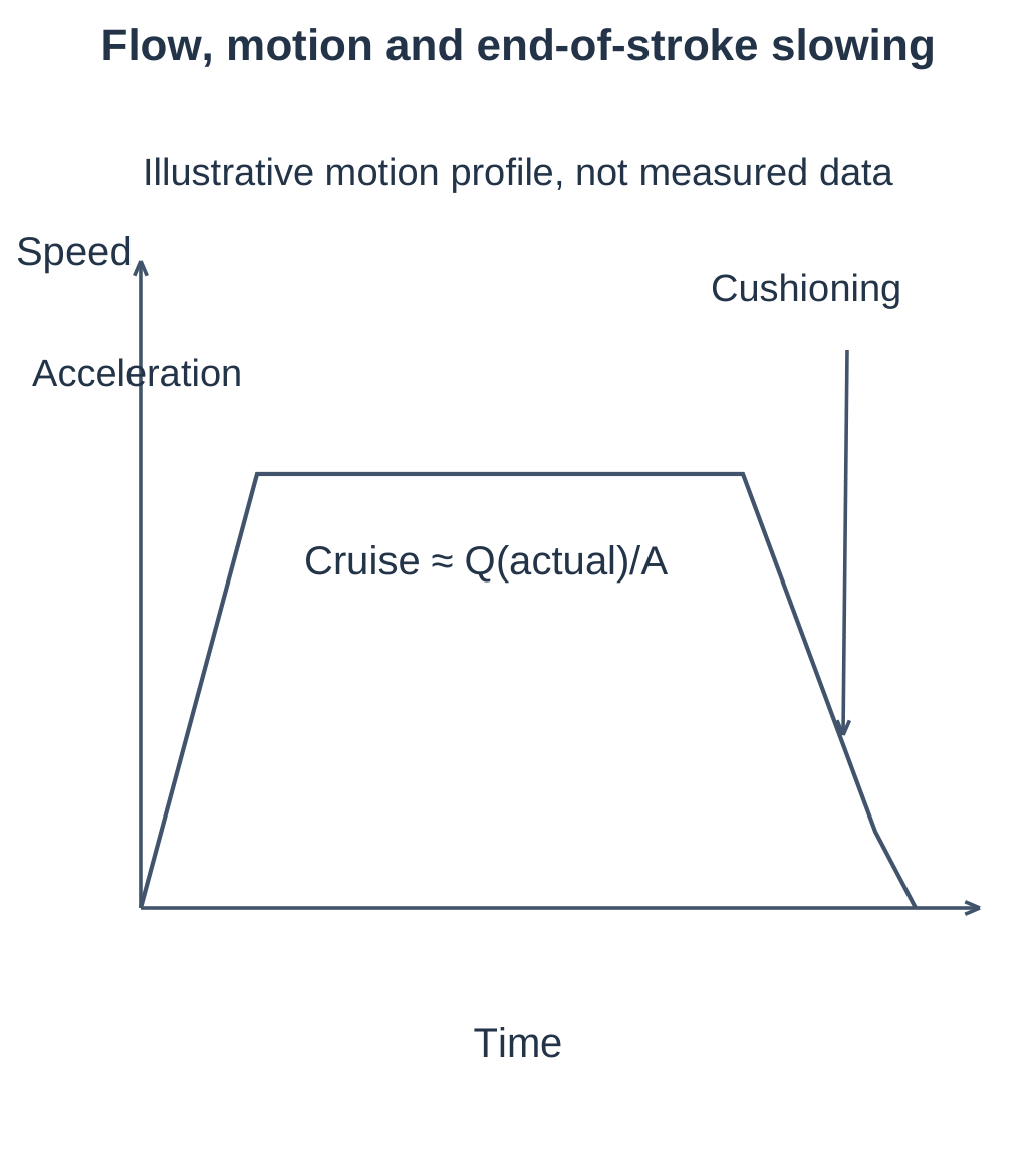
Valve limits, filling transients, load and cushioning affect real stroke time. Convert reference flow to chamber conditions before using it as actual flow.
Reference-Air Consumption
For equal chamber and reference temperatures:
Vref ≈ Vswept × p(abs) / pref
For a double-acting cycle, add both chamber swept volumes.
For D = 40 mm, d = 16 mm and L = 100 mm:
- Cap-end swept volume ≈ 0.1257 L.
- Rod-end swept volume ≈ 0.1056 L.
- At 6 bar gauge and 1 bar atmosphere, pressure ratio = 7.
- Ideal reference consumption = (0.1257 + 0.1056) × 7 ≈ 1.62 L/cycle.
- At 20 cycles/min, ideal demand ≈ 32.4 reference L/min.
Practical estimates include dead space, tubing, leaks and real control behaviour. A complete cycle contains extension and retraction.
5.21 Directional-Valve Notation
The first number gives principal ports; the second gives switching positions.
- 2/2: Two ports and two positions.
- 3/2: Three ports and two positions.
Pilot connections are not counted as extra principal working ports.
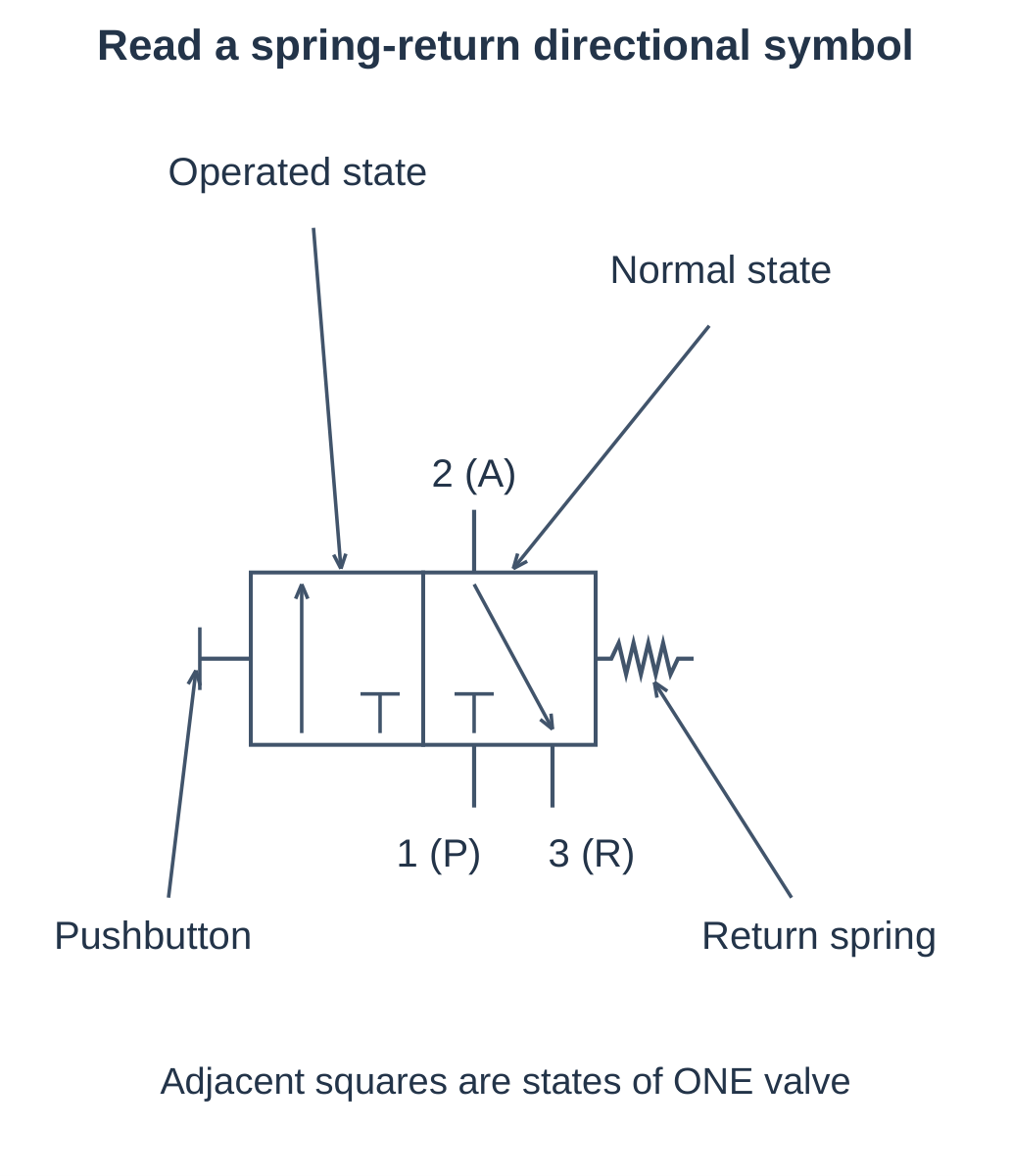
| Port number | Common letter | Function |
|---|---|---|
| 1 | P | Pressure supply |
| 2 | A | Working outlet |
| 3 | R | Exhaust for a 3/2 valve |
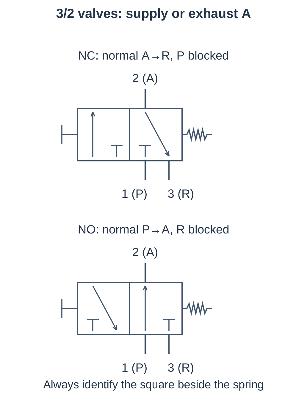
Arrows inside a square show open paths. Short terminating bars show blocked ports. External connections are conventionally shown at the normal-state square.
NC and NO describe the normal supply-to-working-port path. A 3/2 NC valve can still connect A to R normally.
Actuation may be manual, mechanical, solenoid or pneumatic pilot. A spring-return monostable valve returns after command removal when operating conditions permit.
5.22 Two-Port, Two-Position Valves
A 2/2 valve opens or closes the path between ports 1 and 2.
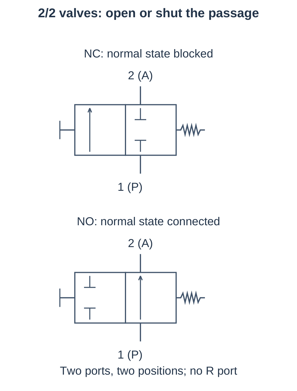
| Command | 2/2 NC | 2/2 NO |
|---|---|---|
| Unactuated | Ports 1 and 2 blocked | 1 connected to 2 |
| Actuated | 1 connected to 2 | Ports 1 and 2 blocked |
Applications include air-branch admission and air-jet switching. Selection depends on pressure, flow, medium and specified reverse-flow behaviour.
Trapped-Air Limitation
Closing a 2/2 valve isolates its outlet; it does not automatically vent the downstream chamber.
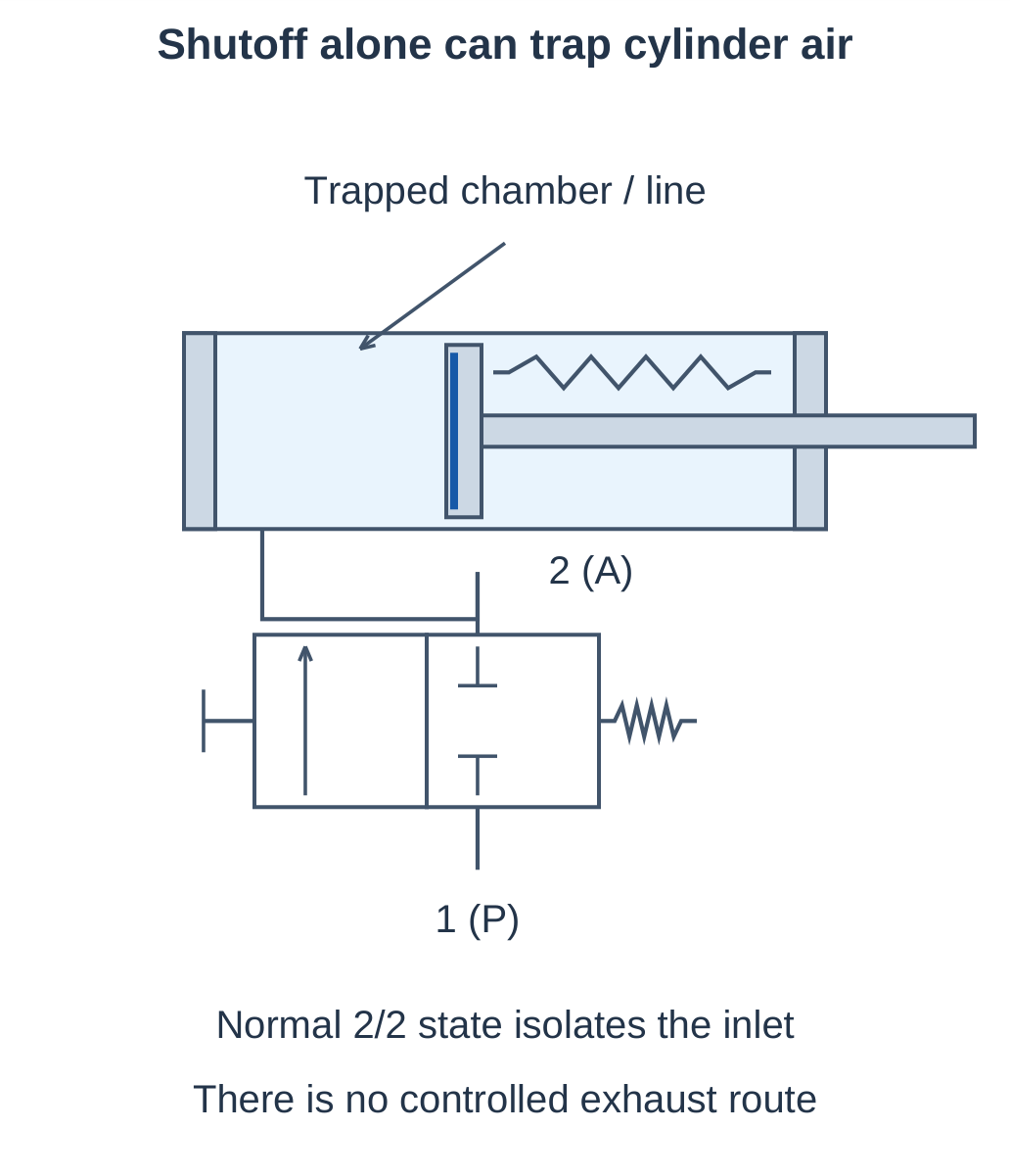
A spring-return cylinder may stay extended or return incompletely if air remains trapped. An additional controlled exhaust route changes the circuit beyond a lone 2/2 shutoff.
Air-Nozzle Example
For an NC 2/2 valve:
- No command: Supply is blocked.
- Command present: Supply reaches the nozzle.
- Command removed: Supply stops; residual line air can escape through the open nozzle.
The nozzle provides the residual discharge path; the valve has not acquired an exhaust port.
5.23 Three-Port, Two-Position Valves
A 3/2 valve switches its working outlet between supply and exhaust.
| Condition | 3/2 NC | 3/2 NO |
|---|---|---|
| Unactuated | 2→3; port 1 blocked | 1→2; port 3 blocked |
| Actuated | 1→2; port 3 blocked | 2→3; port 1 blocked |
Why Exhaust Matters
Connecting A to R allows a cylinder chamber to empty. A spring or external load can then return the piston. Restricted exhaust creates backpressure and can slow or prevent return.
For a pressure-extended, spring-retracted cylinder:
- 3/2 NC: Command ON supplies extension; command OFF permits exhaust and return.
- 3/2 NO: The normal state supplies air; operating the valve vents the chamber.
Read command logic with the hardware normal state.
2/2 and 3/2 Comparison
| Feature | 2/2 valve | 3/2 valve |
|---|---|---|
| Ports | Supply and outlet | Supply, working outlet and exhaust |
| Action | Open or block passage | Supply or exhaust working port |
| Dedicated outlet vent | Absent | Available in exhaust state |
| Single-acting control | Needs an appropriate additional return path | Direct supply-and-exhaust control |
5.24 Single-Acting Actuator Circuit
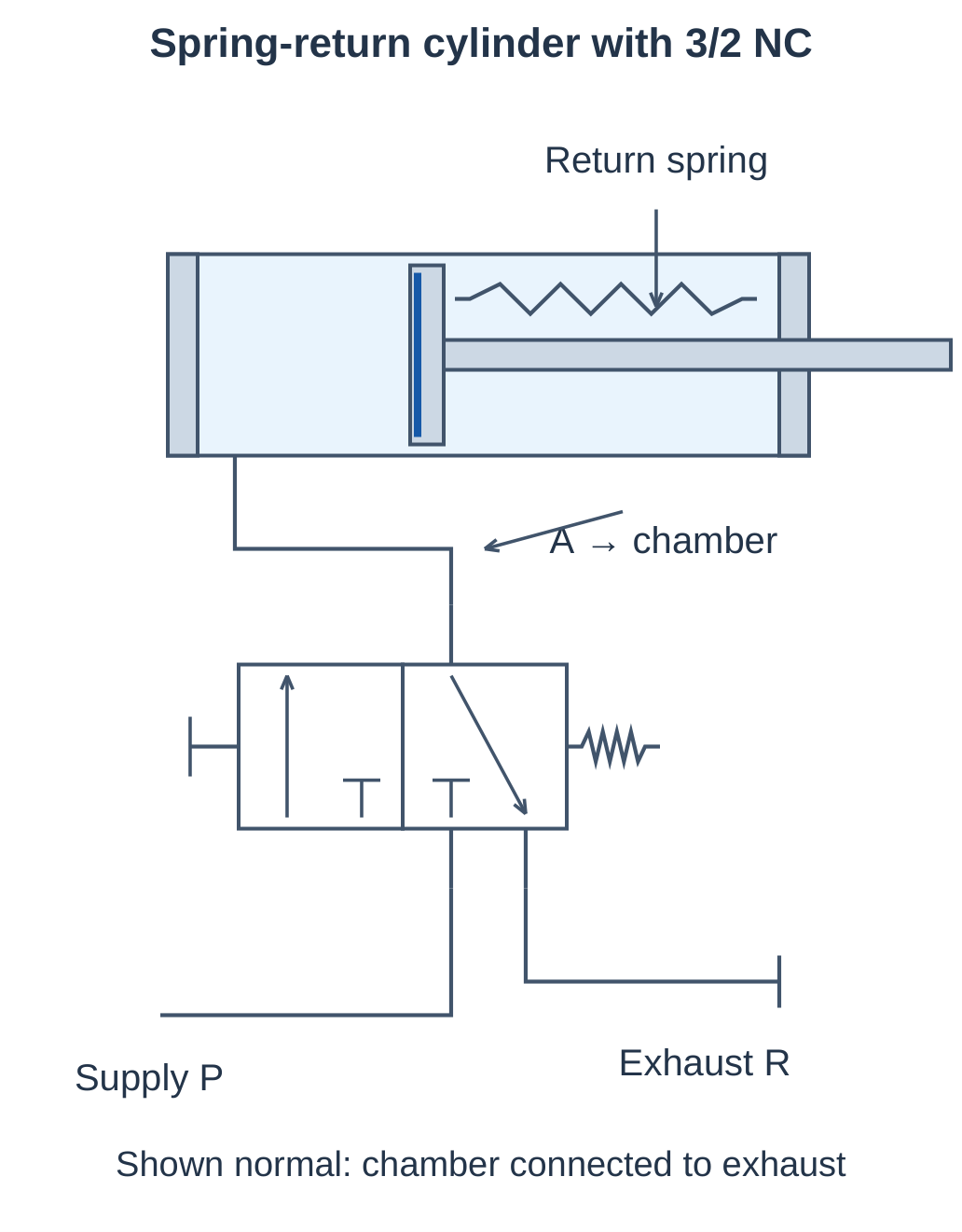
Connect prepared air to P, the working chamber to A, and an appropriate exhaust path to R.
Operating Sequence
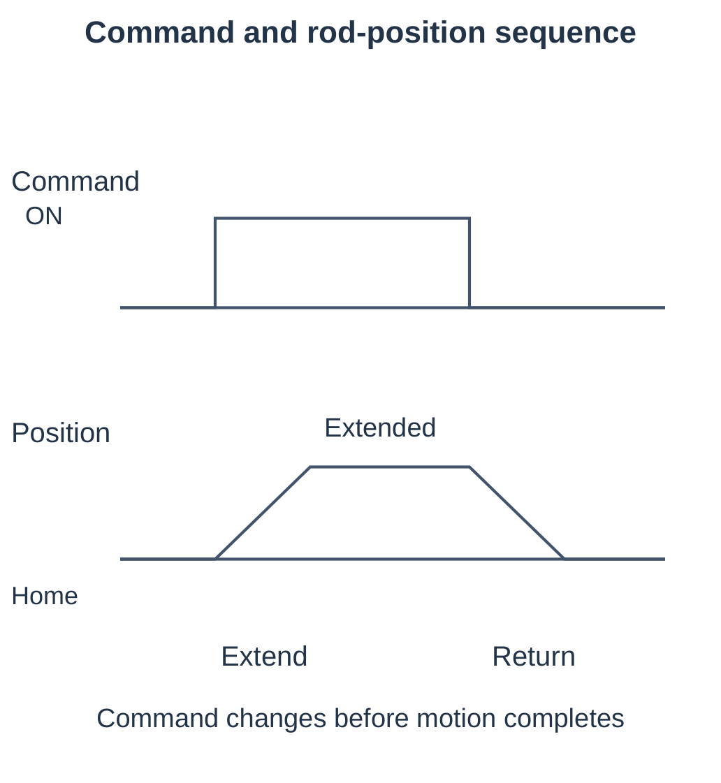
Step 1: Normal state. P is blocked and A connects to R. The spring holds or returns the rod inward.
Step 2: Command applied. P connects to A. Air fills the working chamber and extends the rod if net force is sufficient.
Step 3: Command removed. A reconnects to R. Chamber air exhausts and the spring retracts the rod.
Worked Force Problem
D = 25 mm, chamber pressure = 5 bar gauge, spring force = 35 N and friction = 10 N.
- A = π(0.025)²/4 = 0.0004909 m².
- Pressure force = 500,000 × 0.0004909 ≈ 245 N.
- Available push ≈ 245 − 35 − 10 = 200 N.
A 220 N load will not be driven with these assumed values.
Return-Failure Checks
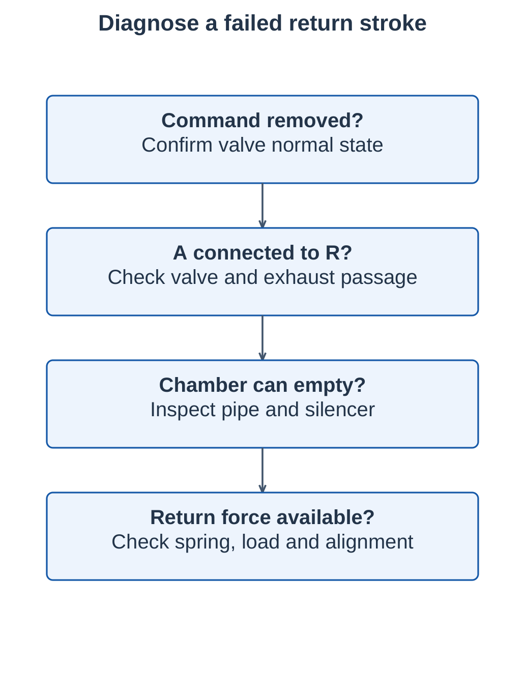
If the cylinder extends but does not retract, check valve reset, A-to-R passage, exhaust silencer, spring force, load and mechanical alignment.
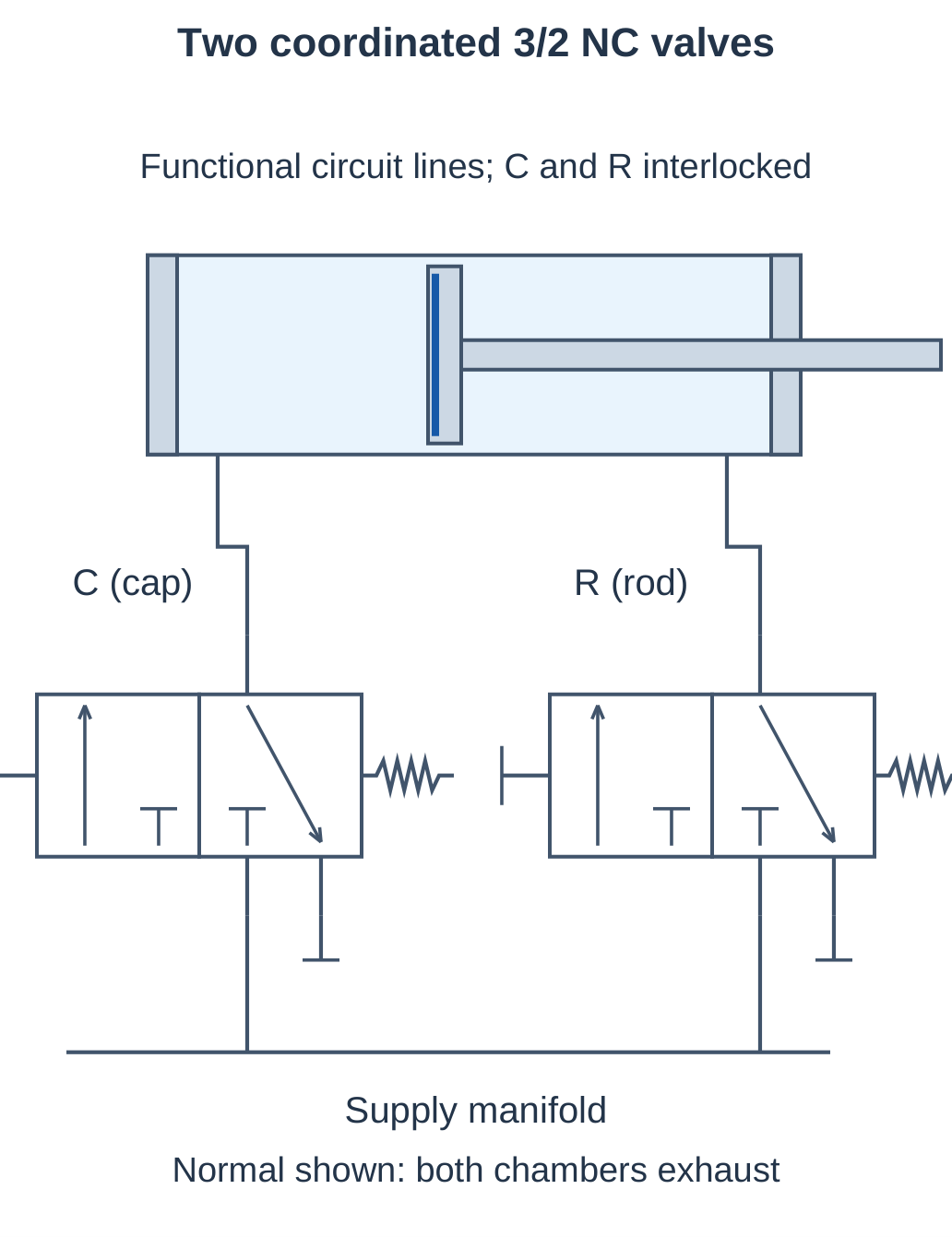
5.25 Double-Acting Control with Two 3/2 Valves
Double-acting motion needs supply to one chamber and exhaust from the other. Common industrial control uses a 5/2 or 4/2 valve. Two coordinated NC 3/2 valves can demonstrate the same chamber-routing requirement, one valve per chamber.
Command-State Table
Here C is the cap-valve command and R is the rod-valve command.
| C | R | Air state |
|---|---|---|
| 0 | 0 | Both chambers exhaust; no pneumatic holding |
| 1 | 0 | Cap supplied, rod exhausted: extend |
| 0 | 1 | Cap exhausted, rod supplied: retract |
| 1 | 1 | Both supplied; avoid as the normal reversal state |
Equal pressure in both chambers does not lock a single-rod piston centrally. Unequal effective areas produce a net pressure force toward extension before load and friction are considered.
Coordination
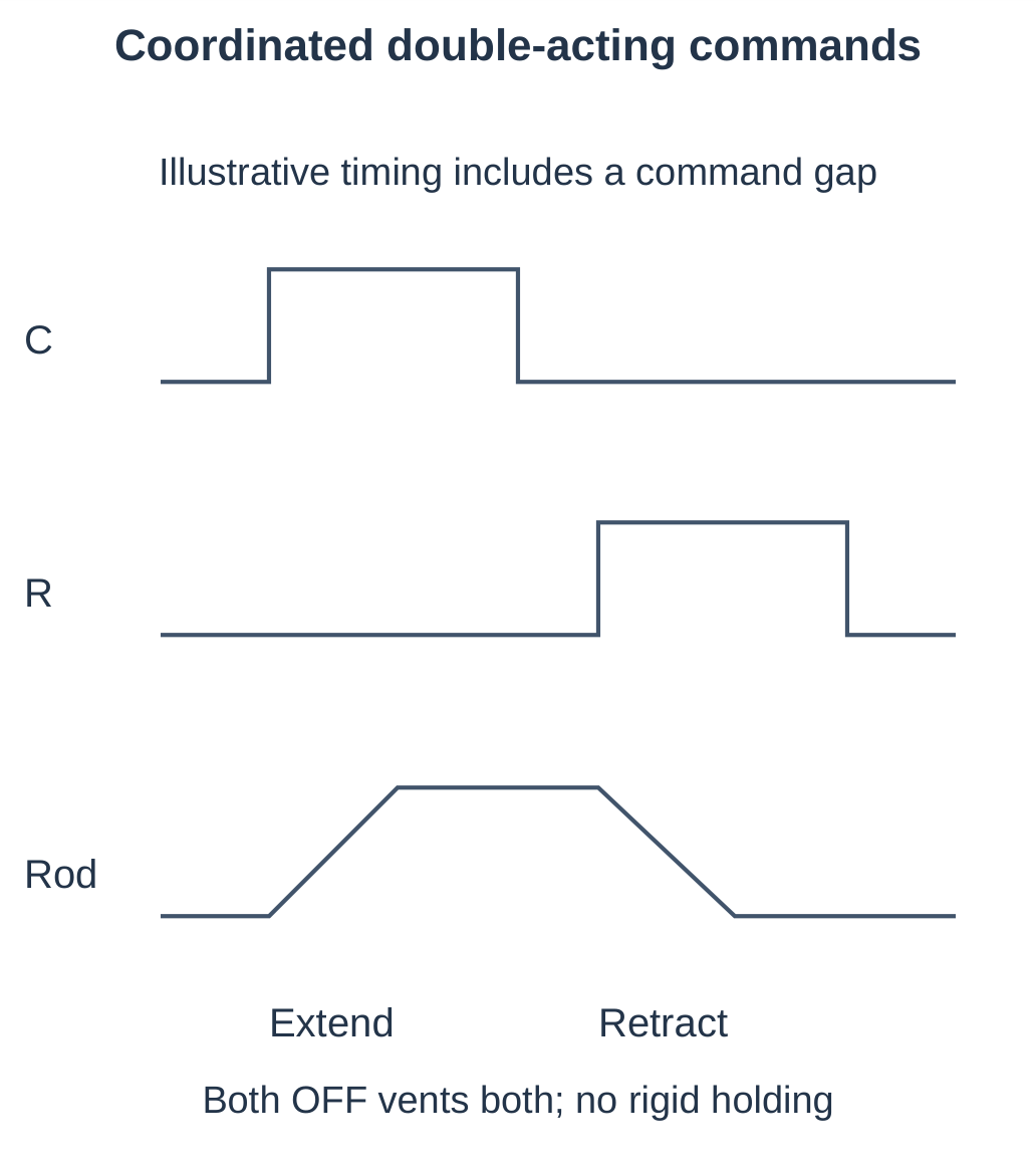
Prevent unintended simultaneous commands and define command-loss behaviour. Reversal requires removing the cap supply command and applying the rod supply command. Pressure changes are not instantaneous.
Logic Example
With C = 0 and R = 1:
- Cap chamber → cap-valve exhaust.
- Supply → rod valve → rod chamber.
- Requested motion: Retraction.
A blocked cap exhaust can reduce retracting force or stop movement despite the correct command.
5.26 Valve–Actuator Problems and Faults
Required Pressure
A spring-return cylinder needs a net 150 N push. Bore is 25 mm, spring force 30 N and friction 15 N.
Required pressure force = 150 + 30 + 15 = 195 N
Required chamber pressure = 195 / 0.0004909 ≈ 397 kPa = 3.97 bar gauge
Upstream pressure must also cover valve and line losses. An upstream setting of exactly 3.97 bar does not guarantee that chamber pressure during a rapid stroke.
Exhaust Backpressure
Ap = 0.001 m², Aa = 0.0008 m², cap pressure = 5 bar gauge and rod pressure = 1.5 bar gauge.
Net pressure force = 500,000 × 0.001 − 150,000 × 0.0008 = 380 N
With 30 N friction:
Available drive ≈ 350 N
Required Flow
Required speed = 0.15 m/s and area = 0.002 m².
Q = Av = 0.002 × 0.15 = 0.0003 m³/s = 18 actual L/min
Compare with valve ratings only after accounting for pressure, temperature and reference conditions.
| Observation | Check | Reason |
|---|---|---|
| No extension | Supply, valve state and load | Insufficient usable chamber force |
| No return | Exhaust, spring and alignment | Trapped air or mechanical resistance |
| Slow both ways | Filter, pipe and valve capacity | Restricted flow |
| Water at exhaust | Dryer and drains | Inadequate moisture treatment |
| Erratic force | Dynamic pressure and leakage | Variable available pressure |
5.27 Worked Automation Station
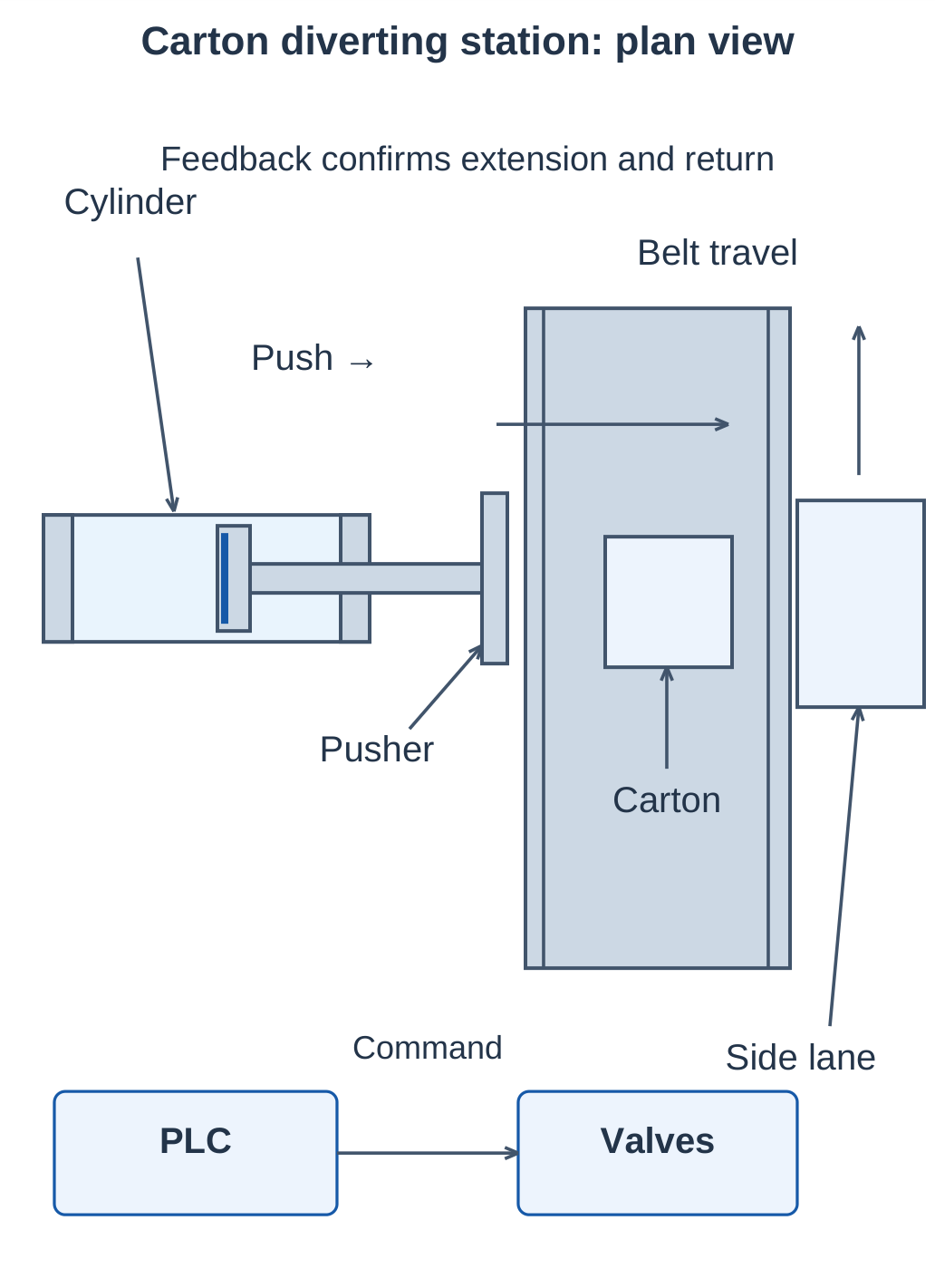
A conveyor detects a carton and operates a pneumatic pusher. The double-acting cylinder diverts the carton into a side lane, retracts and enables the next cycle.
Operating Sequence
- Ready: Rod is home, push zone is clear and adequate pressure is available.
- Detect and position: Identify the carton and pause conveyor permission where required.
- Extend: Command the pusher through the valve system.
- Confirm: Extended-position feedback confirms the push; apply a suitable dwell if needed.
- Retract: Reverse the chamber routing.
- Reset: Wait for home feedback before permitting the next carton.
A timeout indicates incomplete commanded movement. It does not identify the cause by itself. Inspect supply, exhaust, valve, load and feedback paths.
Air-Demand Estimate
D = 32 mm, d = 12 mm, L = 80 mm, pressure = 5 bar gauge, atmosphere = 1 bar and equal temperatures.
- Ap ≈ 0.0008042 m².
- Aa ≈ 0.0006912 m².
- Cycle swept volume = (Ap + Aa) × 0.08 ≈ 0.1196 L.
- Absolute-pressure ratio = 6.
- Ideal reference use = 0.1196 × 6 ≈ 0.718 L/cycle.
- At 30 cycles/min, demand ≈ 21.5 reference L/min.
Add tubing, dead-space, leakage and real-cycle allowances. Multiple stations require assessment of peak flow as well as average demand.
5.28 Quick Revision and Examination Practice
Essential Revision Points
- Pneumatics uses compressed air for power and motion.
- Pressure establishes force potential; actual flow influences speed.
- Boyle’s law holds temperature and mass constant.
- Charles’s law holds pressure and mass constant.
- Gas-law calculations require absolute pressure and kelvin.
- Bernoulli’s elementary equation has constant-density limitations.
- Absolute humidity is vapour mass per volume; RH is a saturation ratio.
- ADP and PDP refer to different pressure conditions.
- Aftercooling and separation remove heat and liquid; drying reduces vapour.
- Receivers buffer demand with finite stored air.
- FRL order is filter, regulator and lubricator where lubrication is required.
- Single-acting cylinders have one powered direction; double-acting cylinders have two.
- Rod-side area is smaller than full piston area in a single-rod cylinder.
- A lone 2/2 shutoff does not provide a controlled exhaust port.
- A 3/2 NC valve normally connects A to R and blocks P.
- Correct double-acting control supplies one chamber while exhausting the other.
- Feedback confirms movement; elapsed time alone does not prove stroke completion.
Important Formulas
| Task | Working relation |
|---|---|
| Pressure | p = F/A |
| Absolute pressure | p(abs) = p(gauge) + p(atmosphere) |
| Kelvin conversion | T = t(°C) + 273.15 |
| Boyle’s law, fixed temperature | p₁V₁ = p₂V₂ |
| Charles’s law, fixed pressure | V₁/T₁ = V₂/T₂ |
| Combined gas law, fixed mass | p₁V₁/T₁ = p₂V₂/T₂ |
| Elementary Bernoulli | p + ½ρv² + ρgz = constant |
| Absolute humidity | ρᵥ = mᵥ/V |
| Relative humidity | RH = 100pᵥ/pₛₐₜ(T) |
| Full piston area | Ap = πD²/4 |
| Annular area | Aa = π(D² − d²)/4 |
| Net extension pressure force | pcAp − prAa |
| Single-acting available push | pgA − Fs − Ff |
| Approximate speed | v = Q(actual)/A |
| Approximate stroke time | t = L/v |
| Reference swept-volume conversion, equal temperatures | Vref ≈ Vswept × p(abs)/pref |
| Receiver release, constant and equal reference temperature | Vref ≈ Vr(p₁ − p₂)/pref |
Numerical Practice with Answers
| Problem | Answer |
|---|---|
| 10 L at 2 bar absolute becomes 4 L isothermally | 5 bar absolute |
| 1.5 L at 300 K reaches 360 K at constant pressure | 1.8 L |
| Vapour partial pressure 1.2 kPa; saturation pressure 3 kPa | RH = 40% |
| 50 mm bore at 4 bar gauge, opposite side at atmosphere | Ideal push ≈ 785 N before friction |
| 3/2 NC released after extension | 2→3; port 1 blocked |
| PDP +2°C; line reaches −5°C at the same pressure | Condensation is possible |
| 100 L receiver falls from 8 to 6 bar absolute; 1 bar reference, equal temperatures | 200 reference L ideally released |
| 25 mm bore at 5 bar gauge; spring 35 N; friction 10 N | Available push ≈ 200 N |
Long-Answer Questions
- Explain an industrial pneumatic installation with a labelled sketch from compressor to actuator.
- State Boyle’s and Charles’s laws with assumptions and worked examples.
- Explain the Bernoulli equation and its limitations in compressed-air systems.
- Distinguish absolute humidity, relative humidity, ADP and PDP.
- Explain reciprocating compressor suction, compression and delivery.
- Compare refrigerated and desiccant dryers with labelled diagrams.
- Explain receiver functions and distinguish relief from working-pressure regulation.
- Explain FRL order, filter construction and regulator feedback.
- Compare single-acting and double-acting cylinders and calculate their forces.
- Draw 2/2 NC and 3/2 NC normal and operated states.
- Explain a spring-return cylinder controlled by a 3/2 NC valve.
- Explain coordinated two-3/2 control of a double-acting cylinder with a state table.
Short-Answer Questions
- Why do gas laws require absolute pressure?
- Why is a Celsius temperature ratio invalid?
- Why does an aftercooler not replace a dryer?
- Why does reheating lower RH without removing more water?
- Why is ideal retracting force lower in a single-rod cylinder?
- Why can a cylinder stay extended after a 2/2 valve closes?
- Which square shows the normal state of a spring-return valve?
- Why does supplying both cylinder chambers not guarantee holding?
- Why must reference flow be converted before calculating chamber speed?
- Why is position feedback useful in a carton-pushing station?
Frequently Asked Questions
What does Industrial Automation and Control Unit 5 cover?
Unit 5 covers pneumatics in automation: gas and flow laws, humidity and dew point, air preparation, compressors, receivers, FRL units, cylinders and directional control valves.
What is the difference between a single-acting and double-acting cylinder?
A single-acting cylinder uses pressure for one direction and a spring or external force for return. A double-acting cylinder uses pressure for both extension and retraction.
What is the correct FRL sequence?
Filter → Regulator → Lubricator. Add lubrication only when required by the connected equipment; suitable prelubricated components may use FR alone.
Can a 2/2 valve directly provide supply and exhaust for a spring-return cylinder?
A lone 2/2 valve has no dedicated exhaust port. A suitable additional exhaust route is needed; a 3/2 valve provides direct supply-and-exhaust switching.
Why are ADP and PDP different?
They describe moisture saturation at different pressures. Converting between them requires pressure and vapour information rather than a fixed temperature subtraction.
How should a pneumatic circuit be studied?
Identify the valve normal state, trace supply to the active chamber, trace exhaust from the opposite chamber, and check load, friction and return forces. Use consistent units and state pressure and temperature assumptions in calculations.