These Industrial Automation and Control Unit 2 Notes explain Automation using Relay Logic for AKTU B.Tech 5th Semester EE and EN students. The unit connects relay construction and contact operation with Boolean logic, memory circuits, contactors, direct-on-line motor starting and practical automation problems. It also explains the development, functional blocks, classification and capabilities of programmable logic controllers.
- University: AKTU
- Course: B.Tech
- Semester: 5th
- Branches: EE and EN
- Subject: Industrial Automation and Control
- Subject Code: BEE053
- Unit: 2 — Automation using Relay Logic
To understand a relay circuit, first trace a complete conducting path to its coil. Then update the associated contacts and check what happens during start, stop, overload, loss of supply and recovery.
Topics Covered in Unit 2
| Topics 2.1–2.10 | Topics 2.11–2.19 |
|---|---|
| 2.1 Automation using relay logic | 2.11 Solving relay automation problems |
| 2.2 Electromagnetic relay construction | 2.12 Tank-filling relay problem |
| 2.3 Contact types and arrangements | 2.13 Permissive conveyor problem |
| 2.4 Types of relays | 2.14 Relay selection and troubleshooting |
| 2.5 Relay circuits as Boolean logic | 2.15 PLC history and development |
| 2.6 Relay as a memory element | 2.16 Basic PLC block diagram |
| 2.7 Contactors and their advantages | 2.17 Classification of PLCs |
| 2.8 DOL starter power circuit | 2.18 Developments in PLC systems |
| 2.9 DOL contactor control circuit | 2.19 Quick revision and exam practice |
| 2.10 Interlocking and sequencing | — |
2.1 Automation Using Relay Logic
Relay logic makes switching decisions through electrically operated contacts and physical wiring. Pushbuttons, limit switches and process switches determine which coils energize. The operated contacts then control loads or create conditions for other coils.
For example, a conveyor may run only when a start command exists, the stop path is healthy and a process permissive is satisfied. Series and parallel contact arrangements implement these requirements.
2.1.1 Control Circuit Versus Power Circuit
| Feature | Control Circuit | Power Circuit |
|---|---|---|
| Main function | Carries control signals and energizes coils | Supplies energy to the motor, heater or other load |
| Typical components | Pushbuttons, auxiliary contacts and coils | Main contacts, load conductors and protective equipment |
| Voltage | Selected control voltage | Required load voltage |
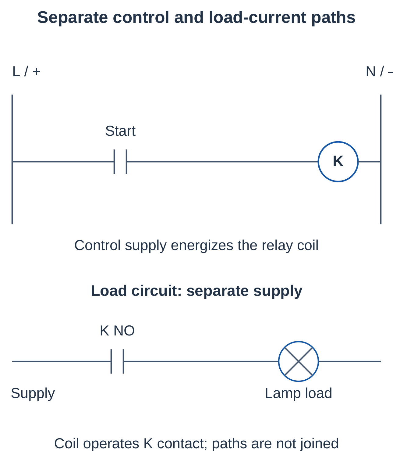
| Motor example | Start button energizes the contactor coil | Contactor main contacts switch motor current |
A small pushbutton normally does not carry the full current of a large motor. The coil and load-current paths perform separate functions, and their supply voltages need not be equal.
2.1.2 Elements and Circuit Notation
| Element | Purpose |
|---|---|
| Pushbutton | Momentary manual input |
| Limit or process switch | Detects position or process condition |
| Relay coil K | Operates associated control contacts |
| Contactor KM | Switches a suitably rated power load |
| Auxiliary contact | Provides feedback, holding or interlocking |
| Overload relay OL | Detects sustained motor overload |
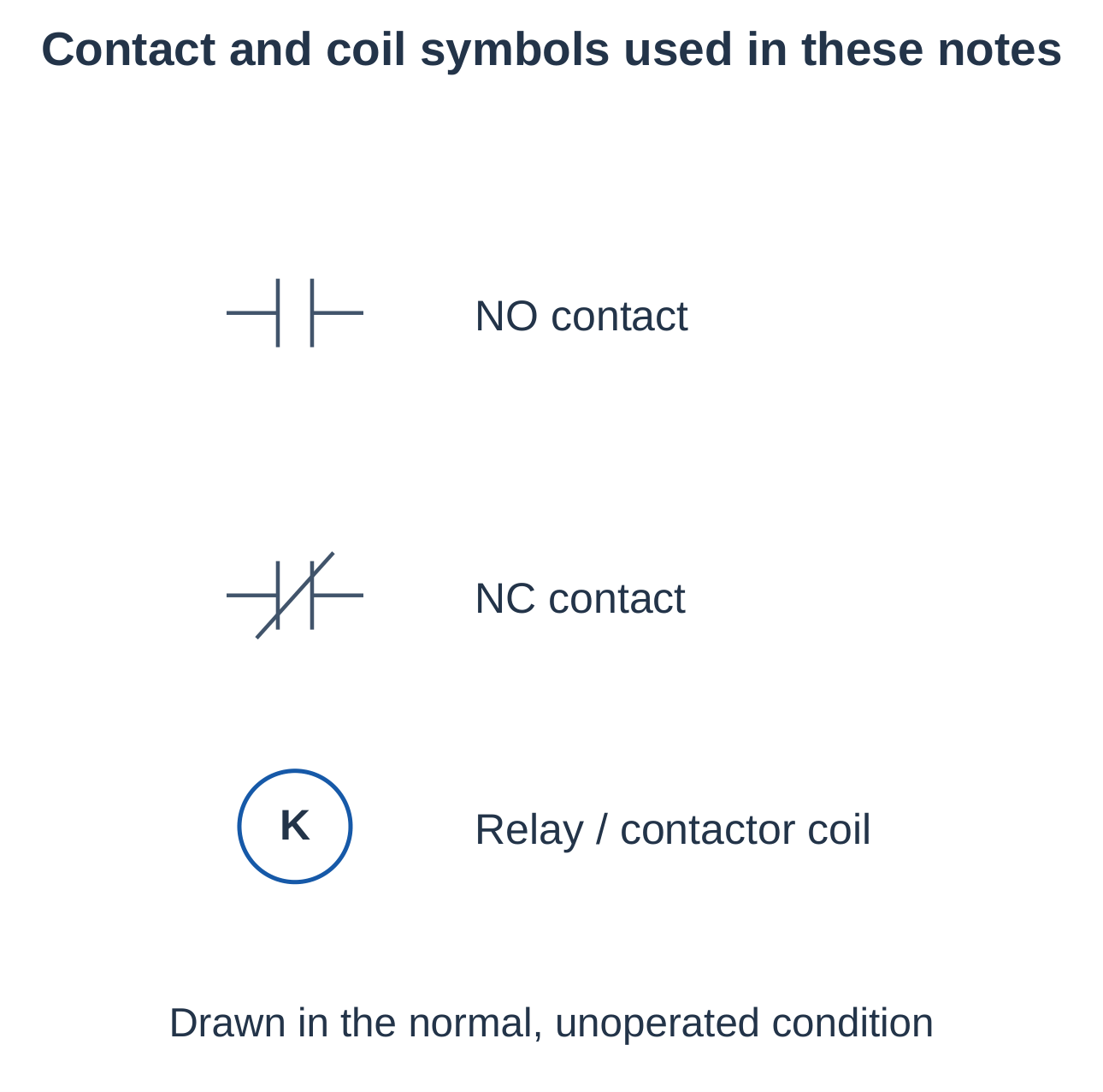
Contacts are drawn in their normal, unoperated condition: the associated coil is de-energized and an ordinary pushbutton is not pressed. Repeated identifiers associate a coil with its contacts. Dashed mechanical links do not represent electrical conductors.
2.1.3 How to Read a Relay Circuit
- Step 1 — Identify the rails: Locate the supply and return.
- Step 2 — Trace the path: Follow closed contacts from supply to coil and return.
- Step 3 — Update contacts: Change every contact associated with the energized coil.
- Step 4 — Check the resulting state: Determine whether the coil stays energized or releases.
A contact labelled K1 belongs to relay K1 even when it appears elsewhere in the drawing.
2.2 Electromagnetic Relay Construction
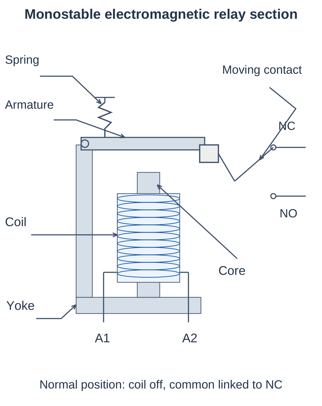
An electromagnetic relay converts coil excitation into mechanical movement that changes contact connections. The coil and contacts are separate functional parts, allowing one circuit to command another within the device’s ratings.
2.2.1 Main Parts
- Coil: Insulated winding that produces a magnetic field.
- Core and yoke: Guide flux through the magnetic circuit.
- Armature: Movable magnetic member attracted during operation.
- Return spring: Restores the normal position in a monostable relay.
- Moving and fixed contacts: Make, break or transfer external connections.
- Insulation, terminals and enclosure: Support separation and external connections.
2.2.2 Operation When Energized
- Step 1 — Apply coil excitation: Current flows through the winding.
- Step 2 — Establish magnetic flux: The core and yoke guide the field.
- Step 3 — Move the armature: Attraction overcomes the opposing spring force.
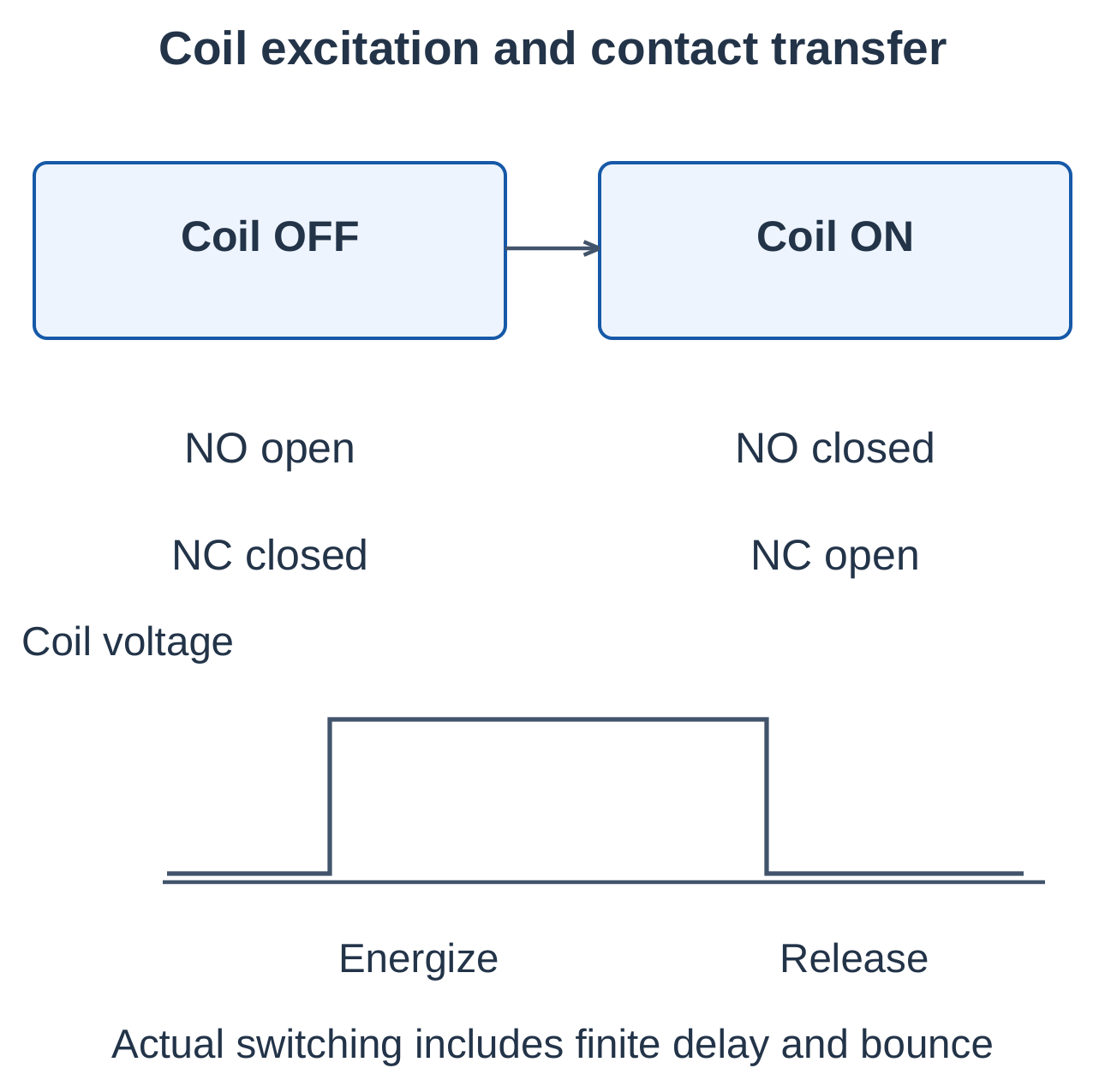
- Step 4 — Transfer contacts: NO contacts close and NC contacts open.
2.2.3 Operation When De-Energized
Magnetic attraction decreases and the spring restores a monostable relay. NO contacts reopen and NC contacts close. A latching relay is an exception: it can retain its selected state after the operating pulse ends.
2.2.4 Practical Behaviour
Operation and release take finite time. Contacts can bounce during transfer. Coil voltage, temperature, mounting and suppression affect behaviour. A relay is therefore not an instantaneous ideal switch when timing matters.
Recall: Electrical excitation → Magnetic attraction → Armature movement → Contact transfer.
2.3 Contact Types and Contact Arrangements
2.3.1 Normally Open and Normally Closed Contacts
- Normally open (NO): Open when unoperated; closed when operated.
- Normally closed (NC): Closed when unoperated; open when operated.
“Normal” describes the specified unoperated state. It does not automatically mean healthy, running or supplied with power.
| Coil State | NO Contact | NC Contact |
|---|---|---|
| De-energized | Open | Closed |
| Energized | Closed | Open |
2.3.2 Changeover Contacts
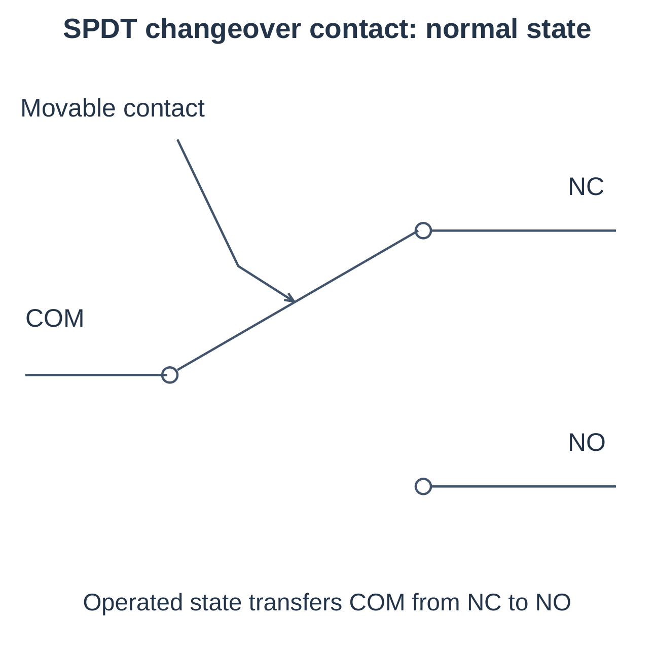
A changeover contact transfers a common terminal (COM) between NC and NO terminals.
| Contact Form | Arrangement |
|---|---|
| Form A | Normally open |
| Form B | Normally closed |
| Form C | Changeover |
Read the actual connection diagram rather than guessing from the package shape.
2.3.3 Pole and Throw
A pole is an independently switched circuit. A throw is an available connection position.
| Arrangement | Meaning |
|---|---|
| SPST | Single pole, single throw: one circuit and one switching connection |
| SPDT | Single pole, double throw: one common transfers between two alternatives |
| DPDT | Double pole, double throw: two independently wired changeover poles operated together |
2.3.4 Main and Auxiliary Contacts
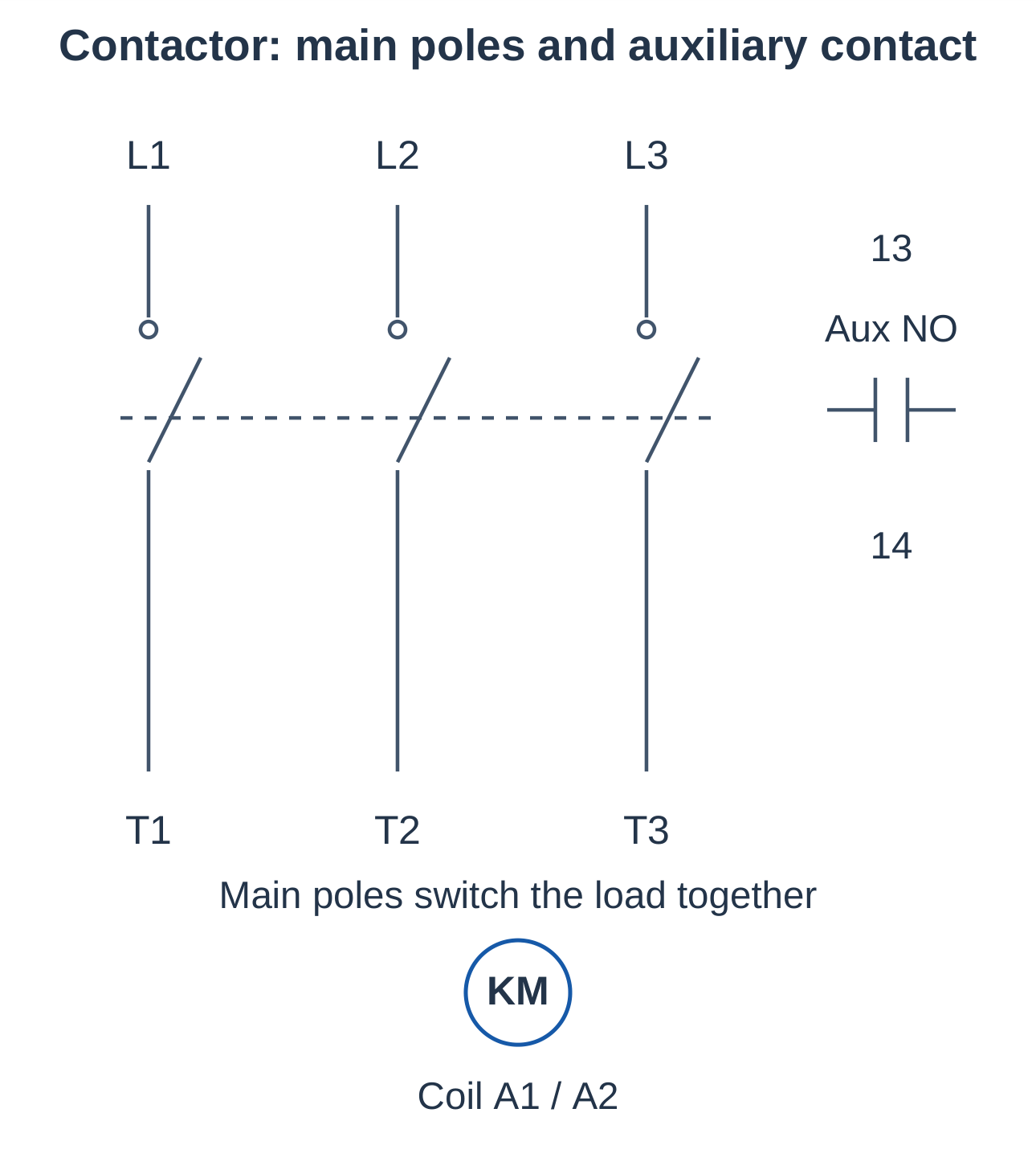
Contactor main contacts switch load current. Auxiliary contacts perform control, indication, holding and interlocking. An auxiliary contact must not be assumed to have the motor-current rating of a main contact.
2.3.5 Terminal Identification
| Common Designation | Typical Meaning |
|---|---|
| A1/A2 | Coil terminals |
| 13/14 | NO auxiliary contact |
| 21/22 | NC auxiliary contact |
| 95/96 | NC overload trip contact |
These are common conventions; verify the actual equipment drawing.
Exam point: An NC stop button opens when pressed. An NO start button closes when pressed. The stop button interrupts a normally complete control path.
2.4 Types of Relays
Relays can be classified by operating principle, timing, stored-state behaviour and application. These categories overlap.
| Type | Operating Idea and Typical Role |
|---|---|
| Electromagnetic | Coil moves contacts for general control switching |
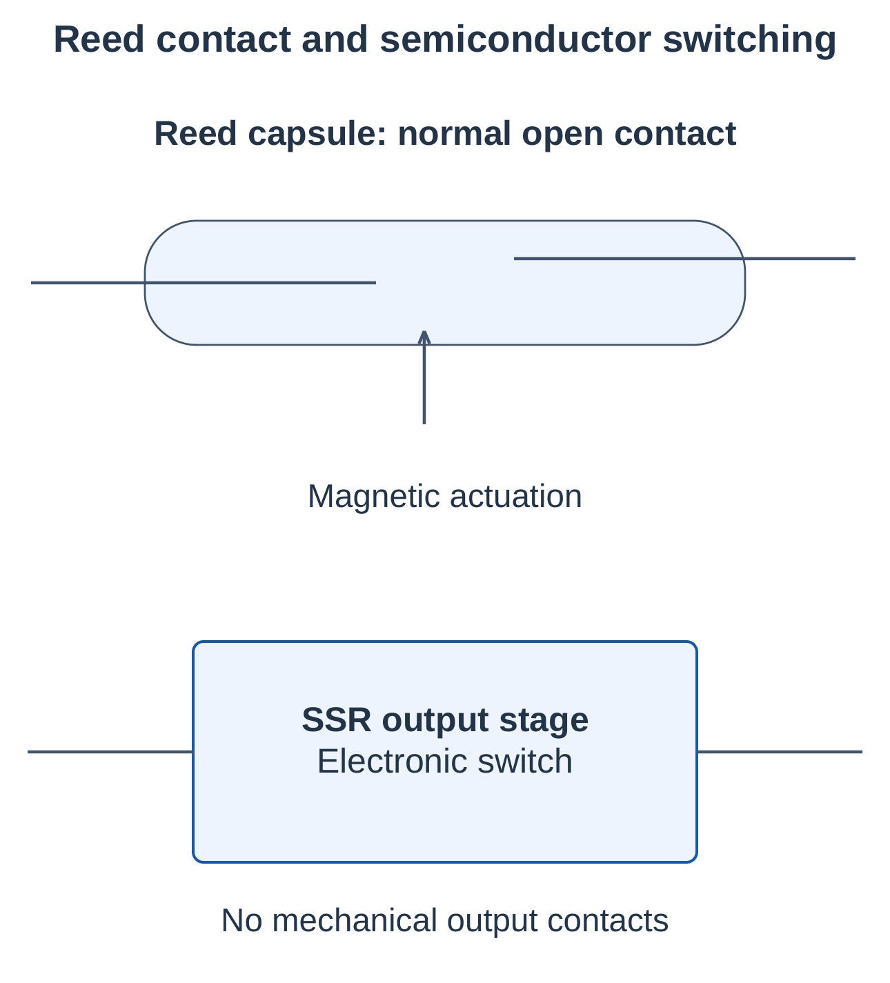
| Reed | Magnetic field operates sealed reed contacts |
| Solid-state relay (SSR) | Semiconductor output switches without moving output contacts |
| Thermal overload | Temperature-related action models motor overload |
| Time-delay | Contacts follow a specified timing function |
| Latching | Retains a selected state after the command pulse |
| Protective | Responds to a specified abnormal electrical condition |
2.4.1 Electromagnetic and Reed Relays
Electromagnetic relays provide control switching between circuits. Reed relays use magnetically operated reeds, commonly enclosed in a sealed capsule. Both require contact ratings suitable for the actual load.
2.4.2 Solid-State Relays
An SSR uses a semiconductor switching arrangement, such as a transistor or thyristor output. It avoids mechanical contact wear and can suit frequent switching.
Consider off-state leakage, on-state voltage drop, heat dissipation and failure modes. An SSR does not provide an ideal open mechanical air gap when off.
2.4.3 Timing Relays
| Function | Behaviour |
|---|---|
| On-delay | Delays timed-contact operation after its timing input becomes active |
| Off-delay | Delays timed-contact return after the controlling signal is removed, according to its supply and trigger arrangement |
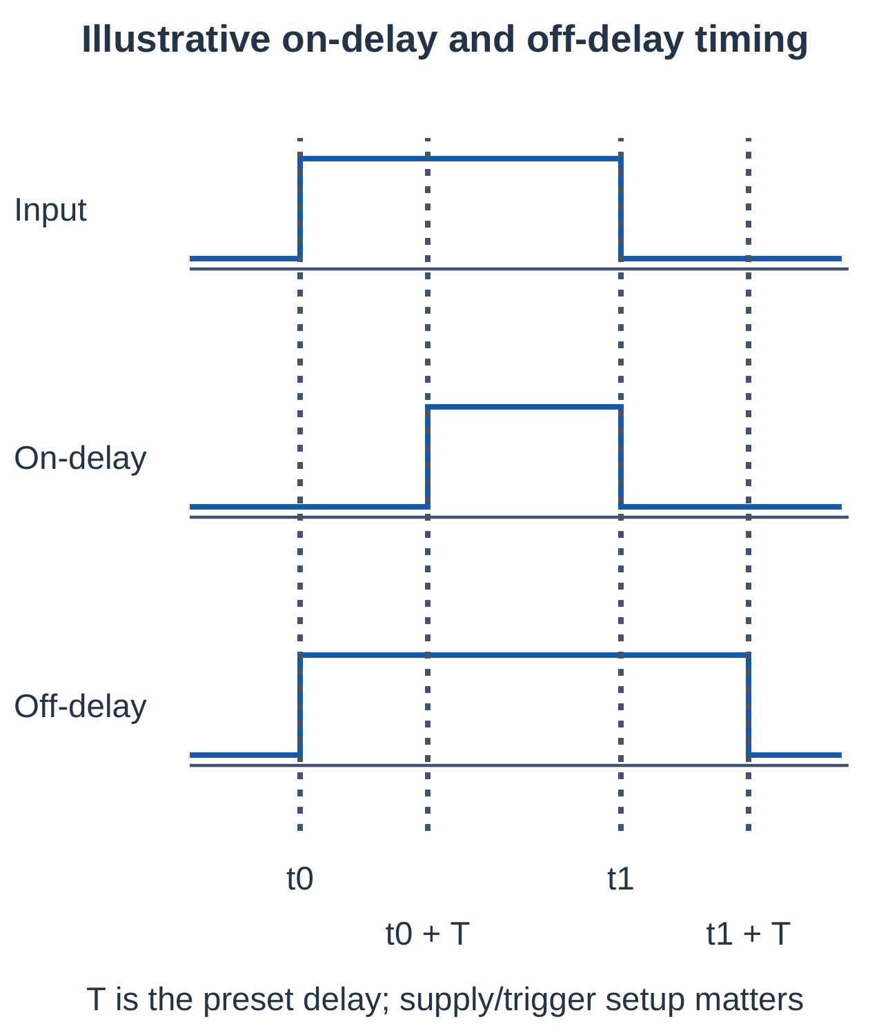
The timing function differs from ordinary mechanical operate time. Some devices need maintained power and a separate trigger, so interpret their timing diagram carefully.
2.4.4 Latching and Protective Relays
A latching relay may use set/reset coils or another bistable mechanism. Protective relays respond to specified faults. A general control relay is not automatically a protective relay or safety relay.
2.4.5 Selection Example
A frequently switched resistive heater may suit a correctly rated SSR with suitable thermal management. A low-frequency control signal may suit an electromagnetic relay. Motor power switching generally needs a motor-rated contactor and coordinated protection.
2.5 Relay Circuits as Boolean Logic
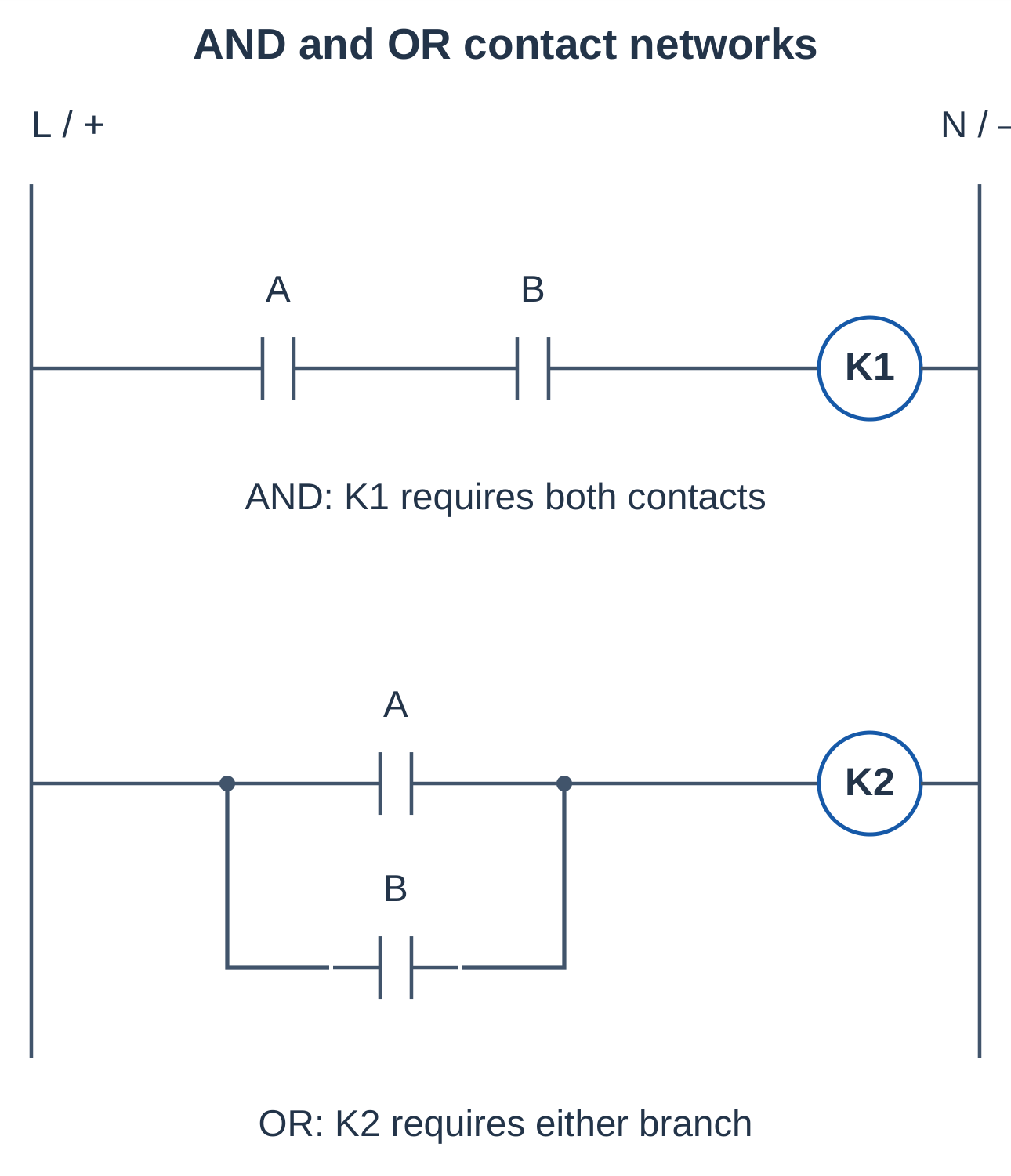
A coil energizes when a complete conducting path exists between supply and return. Series contacts express AND; parallel contacts express OR. An NC contact can express the complement of its relay’s operated state.
2.5.1 AND Function
Two NO contacts A and B in series energize K only when both close.
K = A · B
2.5.2 OR Function
Two NO contacts A and B in parallel allow either branch to energize K.
K = A + B
Here + means logical OR, not arithmetic addition.
| A | B | AND Output | OR Output |
|---|---|---|---|
| 0 | 0 | 0 | 0 |
| 0 | 1 | 0 | 1 |
| 1 | 0 | 0 | 1 |
| 1 | 1 | 1 | 1 |
2.5.3 NOT and Combined Functions
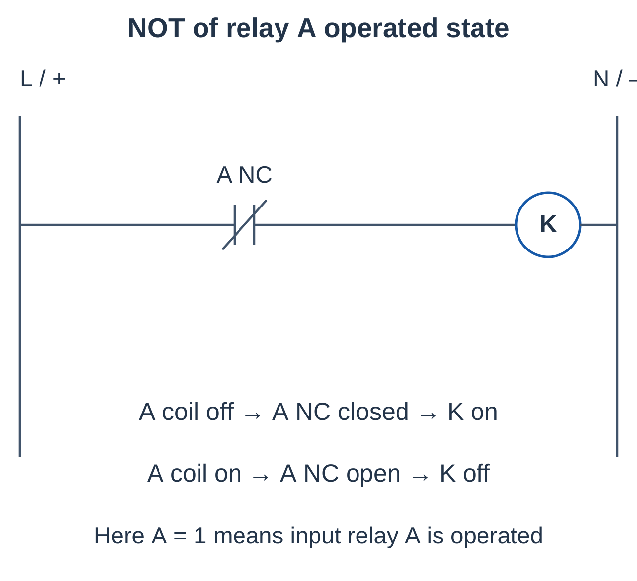
If A = 1 means input relay A is operated, its NC contact conducts when A = 0. Under that definition:
K = NOT A
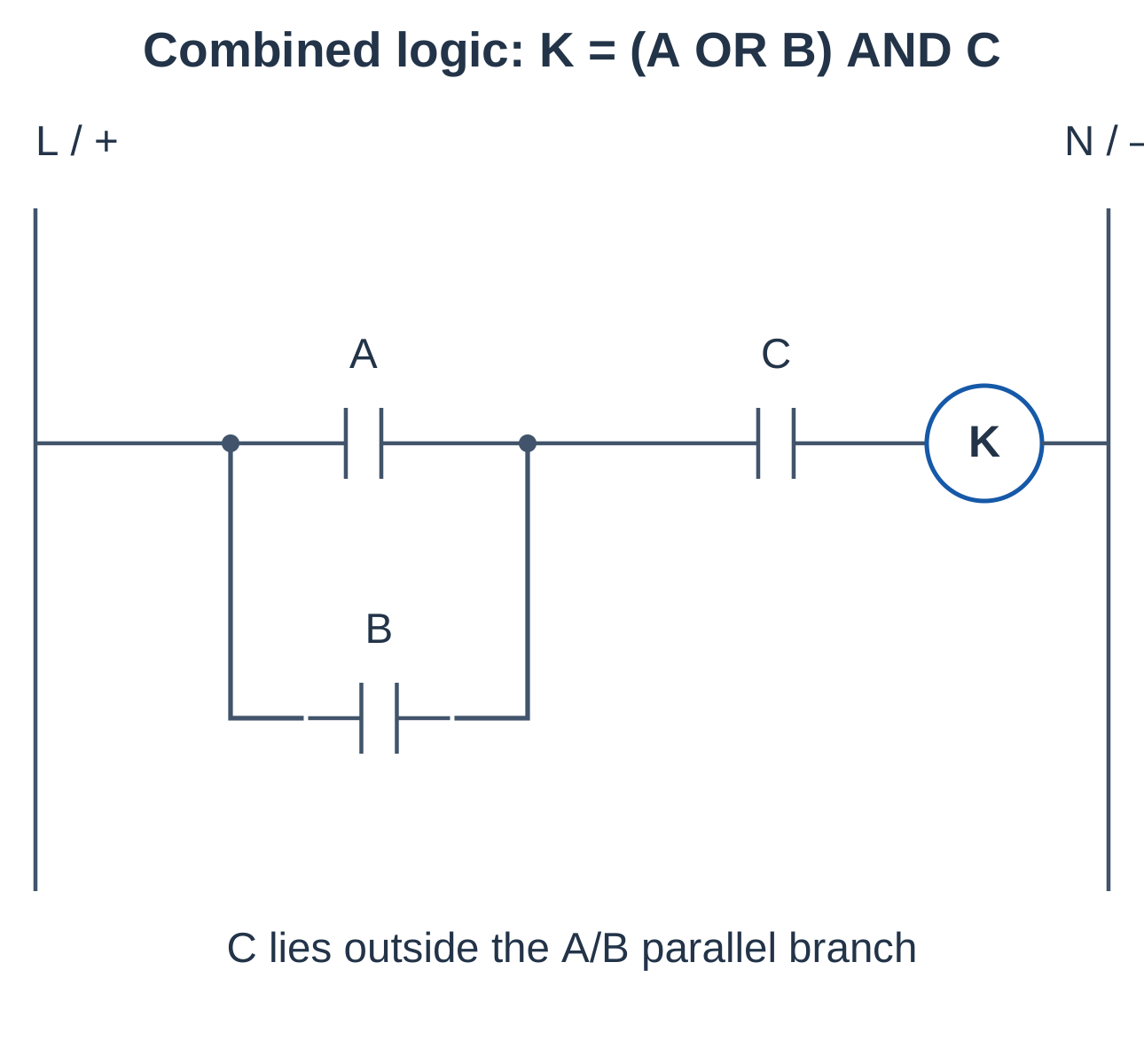
For K = (A + B) · C, place A and B in parallel and put their combined branch in series with C. The C permission must apply to both requests.
2.5.4 Checking the Interpretation
Define what 1 means before writing an equation: energized coil, closed contact, true process condition or PLC bit. These meanings are related but not interchangeable. An NC field switch does not always represent logical zero to a PLC.
2.6 Relay as a Memory Element
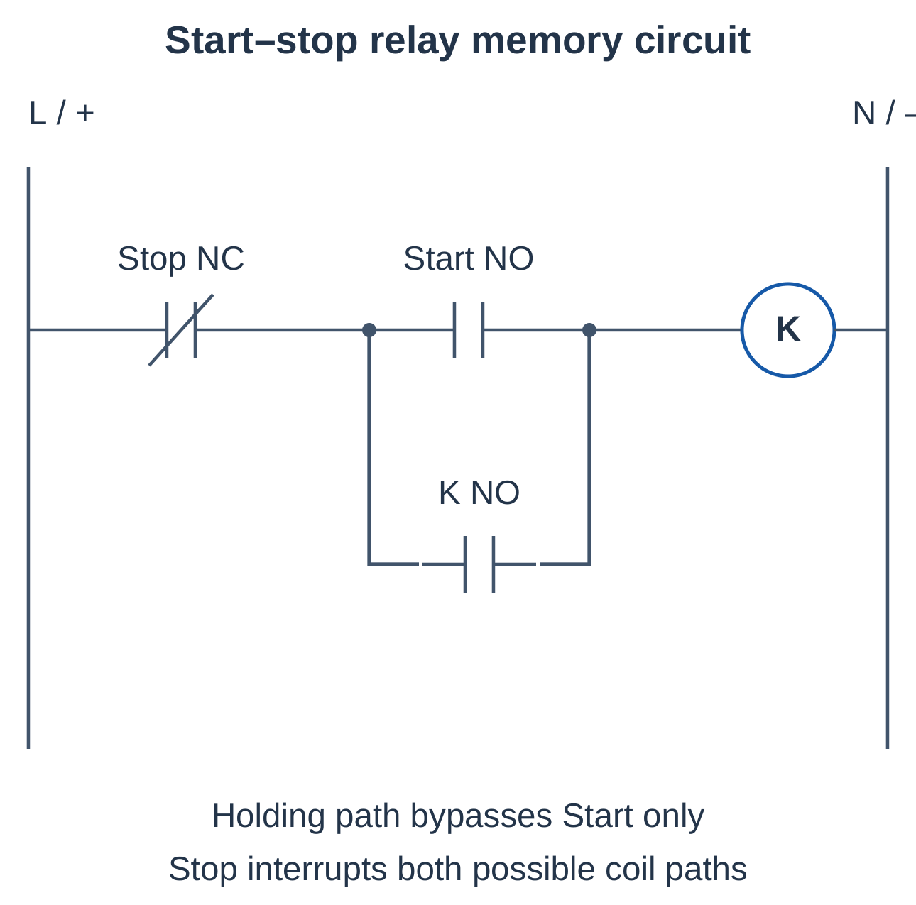
A momentary start can establish a maintained running state through a seal-in, holding or self-maintaining circuit. The relay’s NO auxiliary contact is placed in parallel with the momentary start contact.
2.6.1 Start–Stop Holding Circuit
- Step 1 — Check the stop path: The NC stop contact is closed.
- Step 2 — Press start: The NO start closes and energizes K.
- Step 3 — Establish holding: K’s NO auxiliary closes.
- Step 4 — Release start: The auxiliary path maintains coil current.
2.6.2 Reset and Stop Priority
Pressing stop interrupts K. Its holding contact opens, removing the maintained state. If start and stop are pressed together, the open stop path prevents operation: the circuit is stop-dominant.
Let S = start contact closed and P = stop path healthy.
K(next) = P · [S + K(previous)]
| P | S | Previous K | Next K |
|---|---|---|---|
| 0 | Any | Any | 0: stop path open |
| 1 | 1 | Any | 1: start requested |
| 1 | 0 | 1 | 1: holding maintains operation |
| 1 | 0 | 0 | 0: remains stopped |
2.6.3 Behaviour After Power Loss
An ordinary holding relay releases when coil supply is lost. With start open, it normally remains off after supply restoration until a new start command. A stuck or maintained start changes that behaviour.
2.6.4 Seal-In Versus Bistable Memory
| Feature | Seal-In Circuit | Bistable Latching Relay |
|---|---|---|
| Memory mechanism | Own contact maintains coil current | Bistable mechanism retains selected state |
| Continuous coil supply | Needed to maintain energized state | Not necessarily needed to retain state |
| Supply loss | Normally removes the holding state | Mechanical state can remain |
Neither memory type independently guarantees safe restart. In seal-in logic, the output feeds back into its own input path to store the running decision.
2.7 Contactors and Their Advantages Over Relays
A contactor is an electrically operated switching device designed for suitable power-load duty and repeated operation. It generally has a magnetic operating system, main contacts and auxiliary-contact facilities.
2.7.1 Construction and Operation
Coil excitation attracts the moving magnetic assembly and closes the main contacts. Springs open them when the coil releases. Arc-control structures manage switching arcs within the specified duty.
2.7.2 Advantages for Motor Switching
- Main poles can be selected for motor voltage, current and switching duty.
- Suitable arc-control structures support repeated load switching.
- Multiple poles operate together in a three-phase circuit.
- Auxiliary contacts provide holding, indication and interlocking.
- Accessories support integration with motor starters and overload devices.
2.7.3 Contactor Versus Control Relay
| Feature | Contactor | Control Relay |
|---|---|---|
| Main task | Power switching | Signal and logic switching |
| Contacts | Main power poles plus auxiliaries | Control contacts |
| Duty | Specified power-load category | Specified relay duty |
| Example | Motor starter | Interposing logic |
| Protective equipment | Required as appropriate | Required as appropriate |
A contactor is not automatically better for every task. Small signals and interface functions may be better served by a suitable relay.
2.7.4 Important Limits
A contactor is not a short-circuit protective device. An overload relay does not replace coordinated short-circuit protection. Selection requires voltage, utilization category, operating frequency and environmental conditions, not just nominal current.
2.7.5 Control-Interface Example
When a contactor coil exceeds a PLC output’s permitted voltage or current, the output may operate an interposing relay. Its contact then switches the contactor coil supply. The interface relay’s ratings and suppression must also be suitable.
2.8 Direct-on-Line Motor Starter: Power Circuit
A DOL starter connects a motor directly to its rated line supply through a contactor. It provides full-voltage starting rather than intentionally reducing starting voltage.
2.8.1 Main Components
- Supply isolation and coordinated short-circuit protective equipment.
- Contactor KM with suitable main poles.
- Motor overload device OL.
- Start/stop controls, coil supply and holding auxiliary contact.
- Motor conductors and protective-earth arrangements.
2.8.2 Power Path
Three phase conductors pass through protective equipment, KM main contacts and overload sensing elements to the motor. Overload sensing in the power path is distinct from the NC overload trip contact in the control circuit.
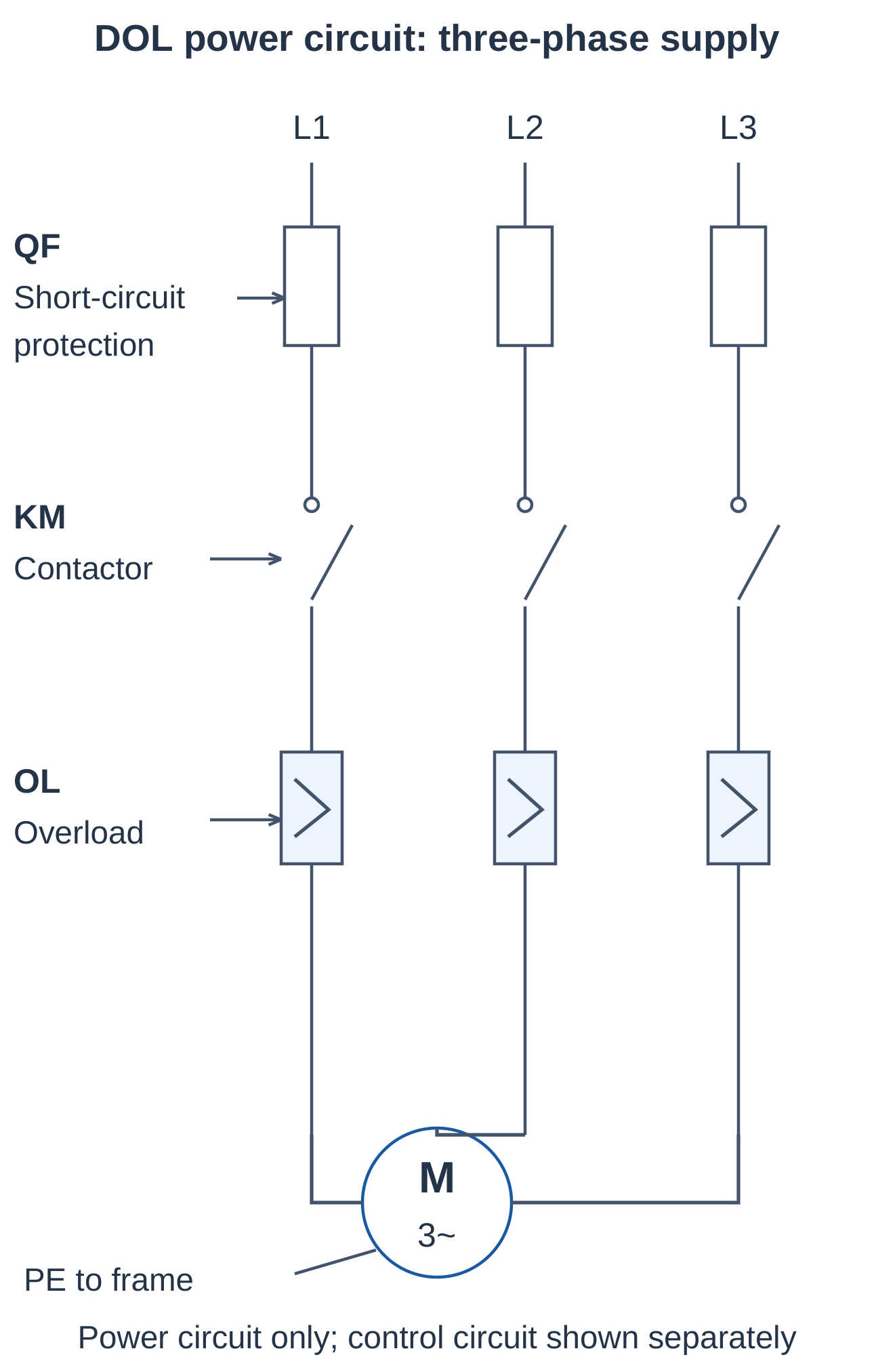
Protective earth is not switched through the operating contactor like a phase conductor.
2.8.3 Starting and Stopping
KM excitation closes the main contacts and supplies the motor. KM release opens them and interrupts its normal supply. Removing power does not stop a rotating motor instantaneously.
2.8.4 Starting Current and Torque
Full-voltage starting can produce substantial starting current and mechanical acceleration. Suitability depends on the motor, supply, driven load and permitted voltage disturbance.
For a stated example with rated current 8 A and assumed starting factor 6:
Starting current = 6 × 8 = 48 A
The multiplier is an example assumption, not a universal constant or setting instruction.
2.8.5 Scope of the Circuit
The diagram explains functional operation. Actual equipment sizing, isolation, protective coordination and safety functions depend on installation requirements. A basic start–stop drawing is not a complete machine electrical design.
2.9 DOL Implementation Using a Contactor
2.9.1 Functional Control Circuit
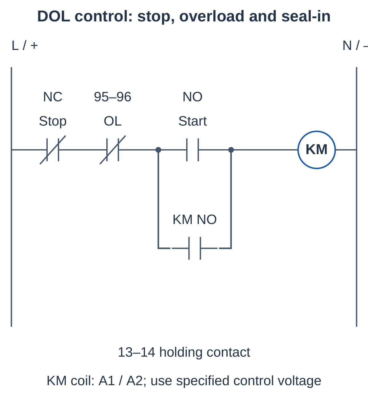
The coil path uses NC stop, NC overload trip, NO start and an NO KM auxiliary contact parallel to start. Stop and overload must interrupt both start and holding paths.
2.9.2 Start Sequence
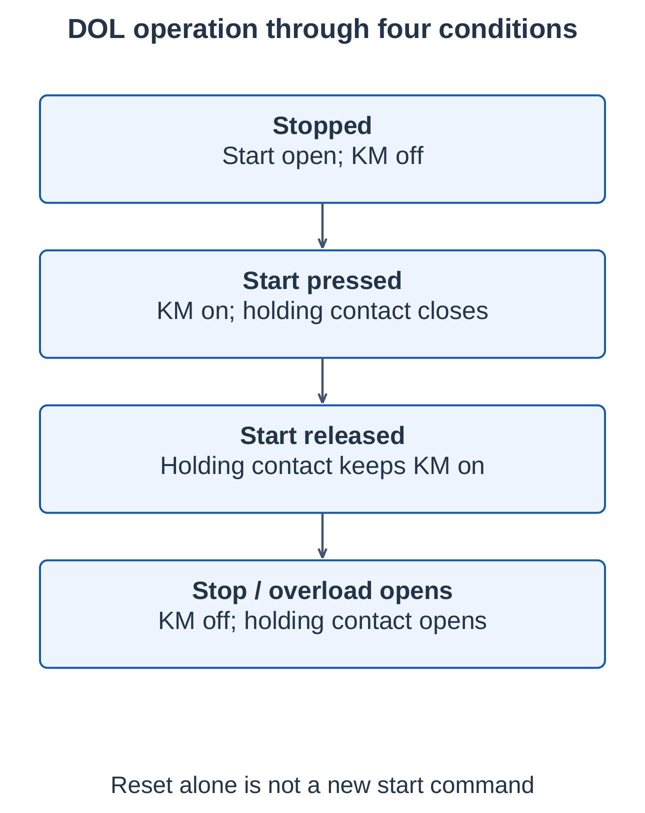
- Step 1 — Establish permissions: Stop and overload contacts are closed.
- Step 2 — Press start: Complete the KM coil path.
- Step 3 — Switch motor power: KM closes its main contacts.
- Step 4 — Close the auxiliary: Establish the holding branch.
- Step 5 — Release start: The auxiliary maintains KM.
2.9.3 Stop Sequence
Pressing stop interrupts the common path. KM releases, main contacts open and the holding contact opens. Releasing stop alone does not restart the illustrated three-wire circuit while start remains open.
2.9.4 Overload Trip
OL operation opens its NC trip contact and releases KM. Resetting OL permits a subsequent start; it does not itself provide a new start command.
2.9.5 Loss of Control Supply
KM normally releases on supply loss. After restoration, a healthy momentary-start circuit remains stopped when start is open. A held or welded start contact changes this behaviour.
2.9.6 Two-Wire Versus Three-Wire Control
| Feature | Two-Wire Control | Three-Wire Control |
|---|---|---|
| Command | Commonly maintained | Momentary start, stop and holding path |
| Supply restoration | May operate again if the command stays closed | Normally requires a new start when start is open |
| Restart assessment | Check maintained-command state | Check start condition and holding arrangement |
Critical placement: A holding contact must not bypass stop or overload; otherwise it can defeat the intended stopping function.
2.10 Interlocking and Sequencing
An interlock prevents an unwanted output combination or sequence. Contacts provide electrical interlocking; suitable mechanical arrangements may provide additional prevention.
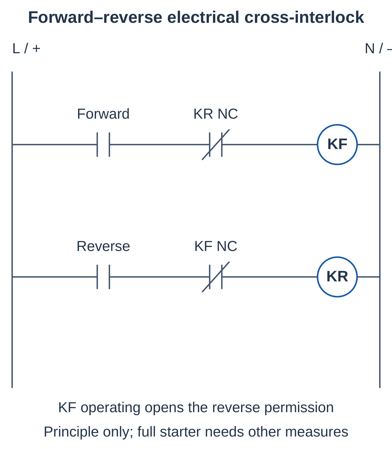
2.10.1 Forward–Reverse Electrical Interlock
Place KR NC in series with forward coil KF and KF NC in series with reverse coil KR. KF operation opens the reverse permission; KR operation opens the forward permission.
2.10.2 Why Mechanical Interlocking Matters
Electrical cross-contacts alone do not guarantee that both contactors can never close under simultaneous commands or faults. A suitable mechanical interlock and complete design address additional hazards. The diagram shows the principle, not a complete reversing starter.
A full starter also needs suitable power connections, holding circuits, stops, overload protection and the intended reversal sequence.
2.10.3 Sequence Permissive
If a feed conveyor may operate only after an extraction fan is running, place the fan-run permissive in the conveyor’s common coil path. Actual fan-run proof is stronger evidence than a fan-start command.
2.10.4 Fault and Recovery Questions
Specify whether loss of a permissive stops operation immediately, initiates a controlled sequence or generates an alarm. Contact placement must implement the required behaviour.
2.10.5 Contacts Versus Process Proof
A contactor auxiliary generally indicates mechanism state. It does not prove motor rotation, belt movement or liquid flow. Use process feedback when that proof is required.
2.11 Solving Automation Problems with Relays
Translate the verbal requirement into input states, outputs and an operating sequence before drawing contact paths.
2.11.1 Design Method
- Step 1 — List inputs and outputs.
- Step 2 — Define normal states and the meaning of each input.
- Step 3 — Write the operating requirement or Boolean equation.
- Step 4 — Identify memory and reset priority.
- Step 5 — Draw contact paths.
- Step 6 — Trace operating, fault and recovery states.
2.11.2 Series and Parallel Placement
A condition required by all start paths belongs outside their parallel branches. A holding contact bypasses only momentary start, not the common stop or essential permissives.
2.11.3 Worked Warning-Lamp Requirement
A warning lamp must operate for either high pressure H or high temperature T, provided monitoring enable E is true.
Lamp = (H + T) · E
Use NO H and T in parallel, followed by common NO E in series with the lamp-driving relay.
2.11.4 Condition Checks
| H | T | E | Lamp Output | Reason |
|---|---|---|---|---|
| 0 | 1 | 1 | 1 | High temperature and enable are present |
| 1 | 0 | 0 | 0 | Enable is absent |
Trace the actual conducting path to confirm the equation.
2.11.5 Documentation
Record coil identifiers, associated contacts, normal states, supply voltage, terminal information and reset assumptions. Use state tables or timing charts when verbal explanation is ambiguous.
2.12 Worked Relay Problem: Tank Filling
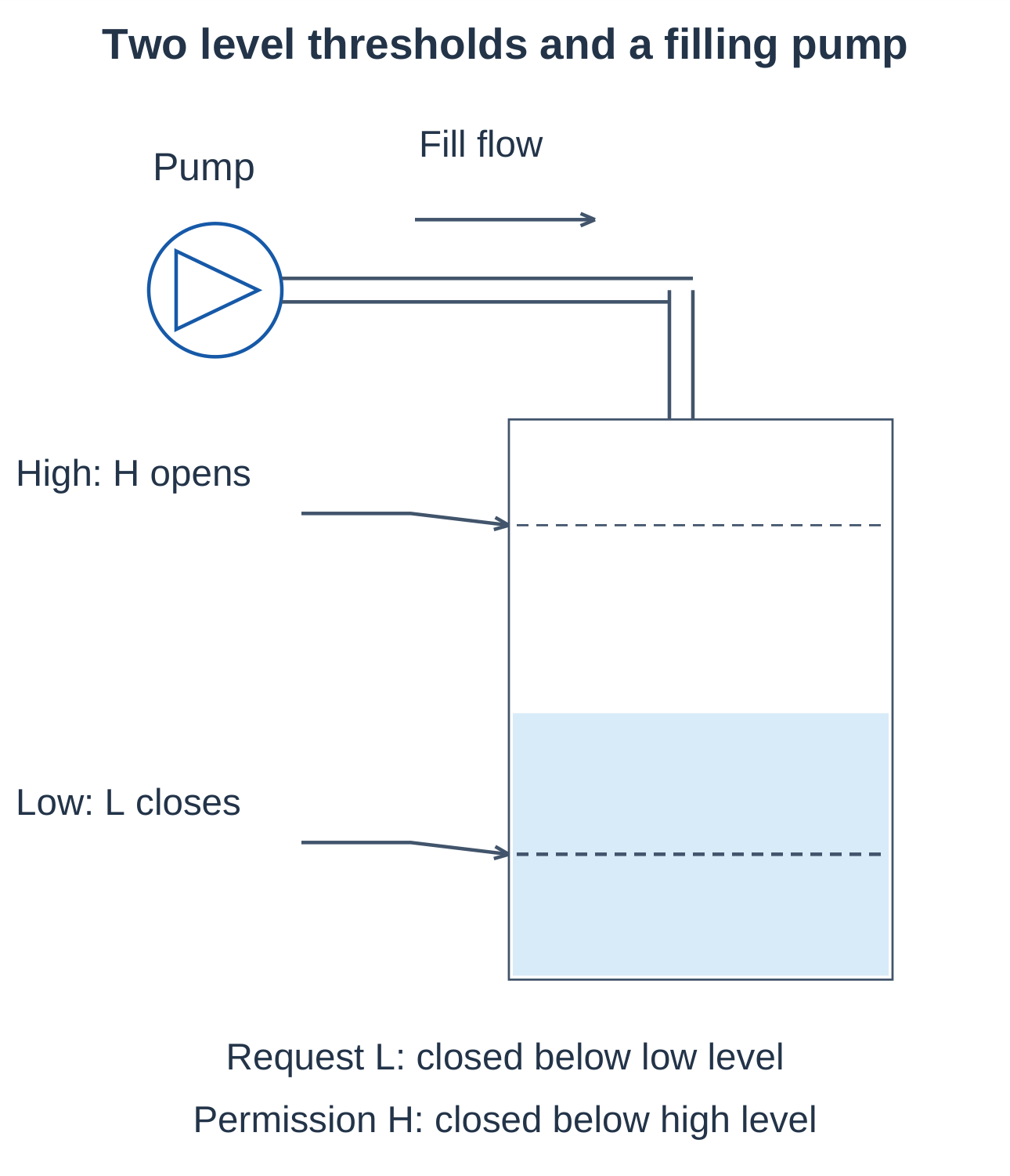
2.12.1 Requirement and Input Definitions
The filling pump starts below a low threshold, remains on while level rises and stops at a high threshold. Manual stop must interrupt pumping at any point.
- L: NO request contact that closes below low level.
- H: Permission contact closed below high level and open at the high threshold.
Actual float mounting and wiring must produce these defined behaviours.
2.12.2 Circuit and Memory
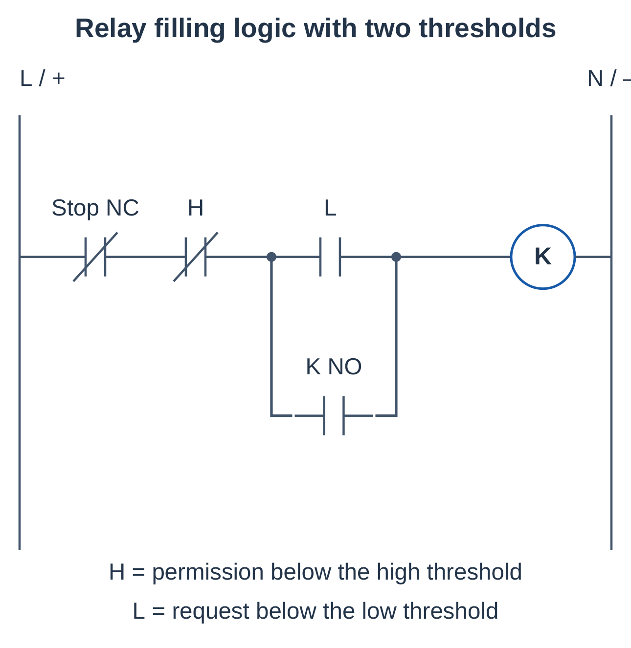
Place NC stop and H in the common series path, with L and K’s NO holding contact in parallel.
K(next) = StopHealthy · H · [L + K(previous)]
2.12.3 Operation Through the Level Band
- Step 1 — Below low level: L closes and starts K when stop and H permit.
- Step 2 — Above low level: L opens, but K’s holding contact maintains pumping.
- Step 3 — At high level: H opens and releases K.
- Step 4 — Level falls: H recloses, but K remains off until L closes below low.
2.12.4 Why Two Thresholds?
Different start and stop thresholds provide an operating band and reduce repeated switching around one threshold. Memory and two level conditions create a functional hysteresis effect.
2.12.5 Edge Cases
After supply restoration between thresholds, K normally remains off because its holding state is lost and L is open. Below low level, L is a maintained automatic request, so restored supply may start the pump. This differs from momentary manual-start control.
Specify dry-running protection, overflow response, sensor-fault handling and restart policy where required. Ordinary logic can act on an incorrect signal from a failed switch.
2.13 Worked Relay Problem: Permissive Conveyor
2.13.1 Requirement
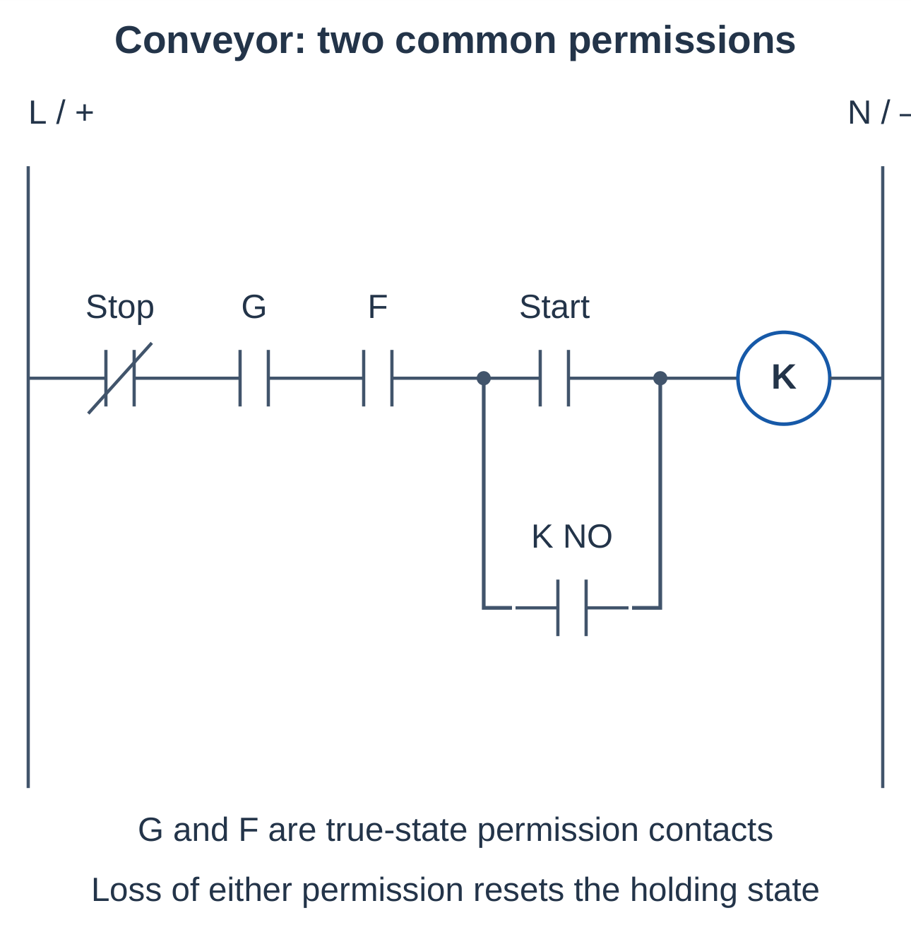
A conveyor starts from a momentary command only when guard-healthy permission G and extraction-run proof F are present. It stops when stop is pressed or either permission disappears.
G and F close when their stated permissions are true. This is a functional example; a real guard safety function may require independently designed safety-related equipment.
2.13.2 Logical Solution
K(next) = StopHealthy · G · F · [Start + K(previous)]
Stop, G and F belong in the common series path. Start and K’s holding contact are parallel after those permissions.
2.13.3 Test Cases
| Condition | Expected Response |
|---|---|
| Start pressed; all permissions true | K operates and holds |
| Start released after operation | K remains on |
| F disappears while running | K releases |
| F returns with start open | K remains off |
| Stop and start pressed together | K remains off |
2.13.4 Fault Diagnosis
If fan proof disappears, identify which input opened before assuming a contactor fault. A labelled circuit separates an intended permissive stop from supply, coil or wiring failure.
2.13.5 Additional Start and Stop Positions
A second NO start can be parallel to the first. A second NC stop belongs in series with the first stop. All start positions must still require the common permissions.
2.14 Relay Selection and Troubleshooting
2.14.1 Electrical Selection
Check coil voltage, AC/DC type, coil power, contact arrangement, load voltage and switching duty. A resistive-load current rating is not automatically valid for motor starting, lamp inrush or inductive switching.
For an illustrative 24 V DC, 2.4 W coil:
Steady current = P ÷ V = 2.4 ÷ 24 = 0.10 A
This calculation does not describe AC-coil inrush or every electronic coil design.
2.14.2 Inductive Switching
Coils store magnetic energy. Interrupting current can create a voltage transient. Suitable suppression protects the driver, but can affect release behaviour.
A diode across a DC coil is normally reverse-biased during energization. Do not use the same diode arrangement across an AC coil. Select suppression approved for the actual coil and required release performance.
2.14.3 Mechanical and Contact Issues
Bounce, contamination, wear and welding can change switching behaviour. Check loose terminals, inadequate coil voltage, incorrect ratings and chatter. Energized coils do not prove every contact has switched correctly.
2.14.4 Fault-Finding Sequence
- Step 1 — Establish the reported state.
- Step 2 — Check control supply.
- Step 3 — Trace stop, trip and permissive contacts.
- Step 4 — Verify command and coil voltage.
- Step 5 — Inspect associated contact action.
- Step 6 — Check load path and feedback.
| Symptom | Possible Explanation |
|---|---|
| Operates only while start is held | Holding path open or incorrectly wired |
| Will not start | Open stop, trip or permissive; missing supply; coil fault |
| Will not stop normally | Bypassed stop, welded contact or wrong holding branch |
| Repeated chatter | Unstable coil voltage or control condition |
| Coil on but motor off | Power-path, contact or motor fault |
These are possible causes, not unique diagnoses. Use observations to narrow the fault.
2.15 PLC Introduction: History and Development
A programmable logic controller (PLC) reads field inputs, executes a stored program and updates outputs. It retains contact-and-coil reasoning while implementing much of the decision logic in software.
2.15.1 Why PLCs Were Needed
Large relay panels required extensive wiring. Sequence changes could need rewiring, retesting and documentation updates. Contact wear, cabinet space and fault tracing increased maintenance work.
PLCs allow many logical changes through the program, while field wiring and power switching remain necessary.
2.15.2 Early Development
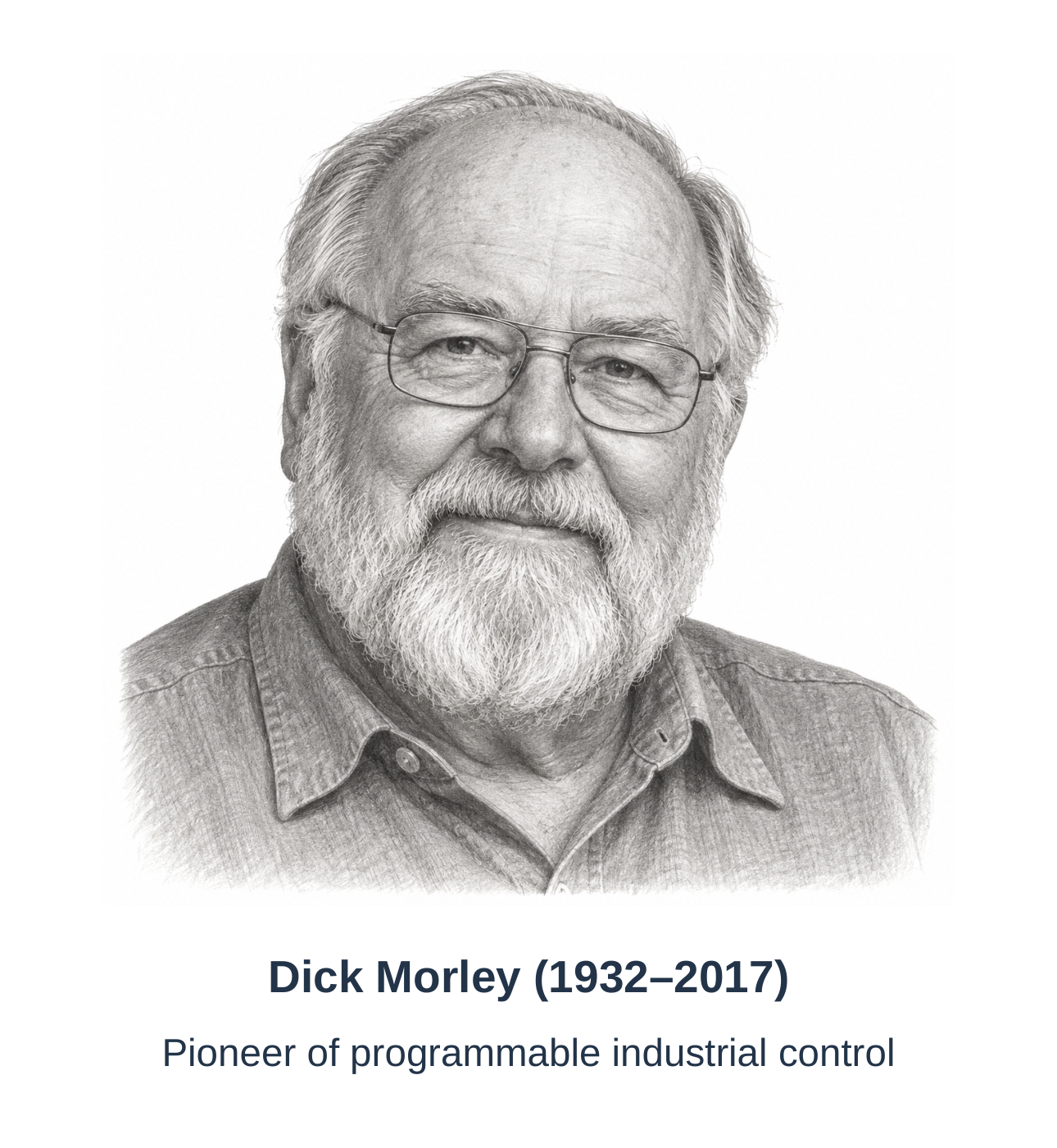
Programmable industrial controllers emerged in the late 1960s as alternatives to hardwired relay control. The Modicon 084 is a landmark early controller associated with Dick Morley and the Bedford Associates team. Modicon derives from Modular Digital Controller.
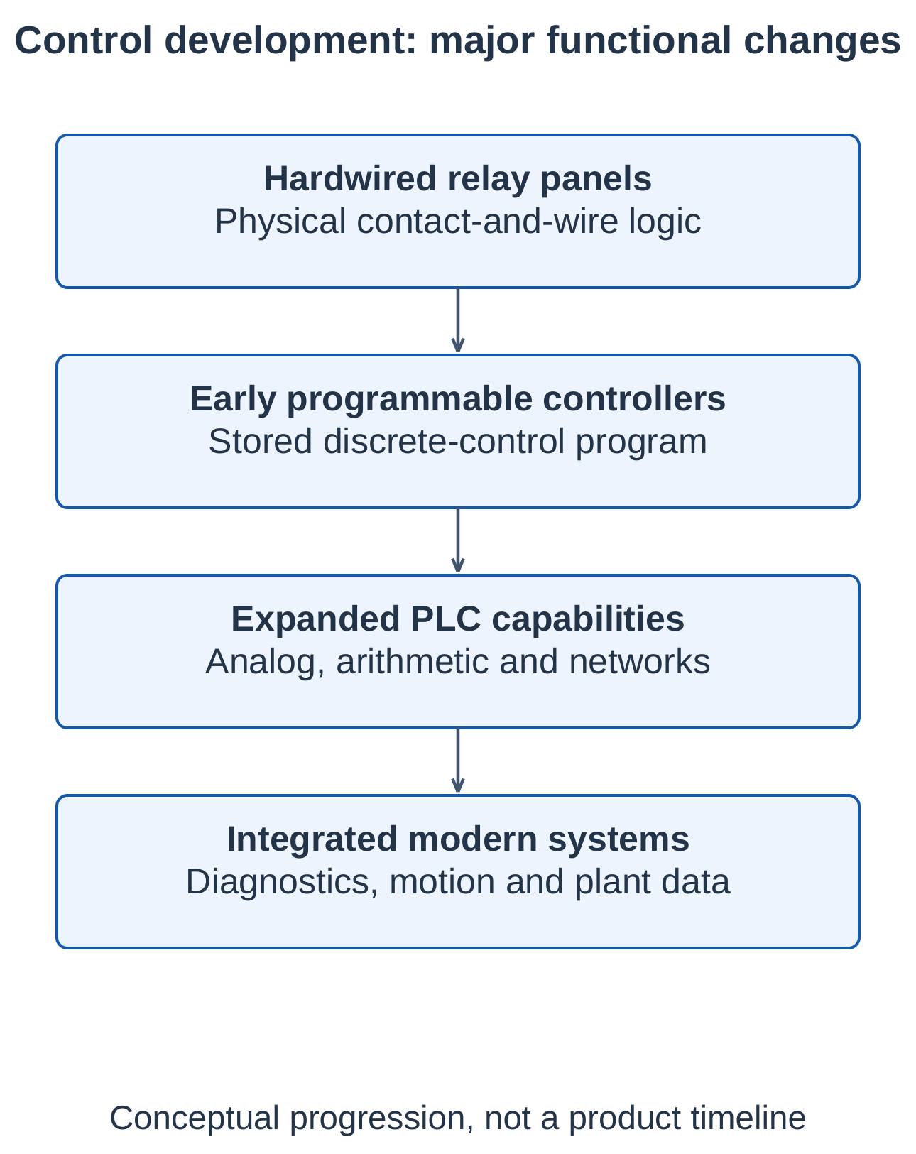
2.15.3 Evolution of Functions
Early applications emphasized discrete logic. Capabilities expanded to timing, counting, arithmetic, analog processing, communication, regulation and coordinated machine functions. Networks connected controllers with remote I/O and supervision.
2.15.4 What Changed and What Remained
Decisions moved increasingly into software. Sensors still measure conditions, interfaces still require suitable ratings and contactors commonly switch motor power. A PLC does not eliminate every relay or the physical process.
2.15.5 Historical Answer Structure
Explain the problems of hardwired panels, the emergence of programmable industrial control, relay-like programming and expanded capabilities. History is more useful as an explanation of development than a list of model names.
2.16 Basic Block Diagram of a PLC
2.16.1 Functional Blocks
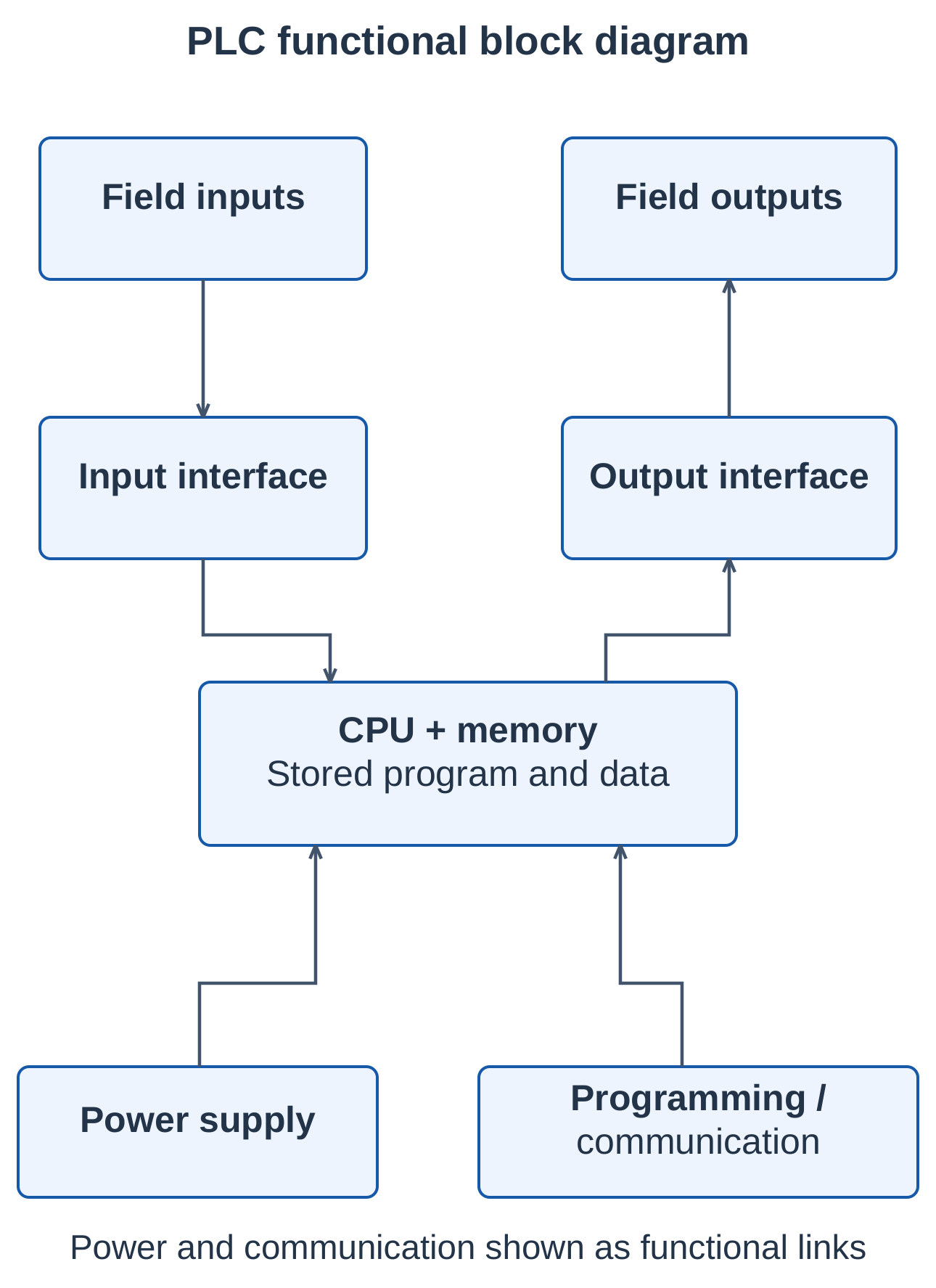
| Block | Function |
|---|---|
| Power supply | Provides operating power |
| Input interface | Converts field signals into controller information |
| CPU | Executes the program and coordinates tasks |
| Memory | Stores program, working data and configuration |
| Output interface | Converts decisions into suitable electrical outputs |
| Programming and communication facilities | Support engineering and external data exchange |
2.16.2 Input Interface
Input circuits provide suitable electrical interfacing and may include isolation, filtering or conversion. Digital inputs represent states; analog inputs represent quantities within a configured range.
2.16.3 CPU and Memory
The CPU executes instructions and coordinates system tasks. Memory stores program, data and configuration. Retention and restart depend on the controller and settings; not every bit survives every supply loss.
2.16.4 Output Interface
Relay, transistor and triac outputs have different limitations. Outputs must match field circuits, and large loads generally need correctly rated interface and power-switching equipment.
2.16.5 Programming and Communication
An engineering station supports programming, configuration, diagnosis and maintenance. Communication connects other controllers, remote I/O and HMI/SCADA. The programming device normally need not remain connected for standalone operation.
2.16.6 Basic Operating Cycle
The conventional model updates inputs, executes logic and updates outputs, with diagnostic and communication work also performed. Actual scan order, immediate I/O and scheduling vary. Programming details are developed in Unit 3.
2.17 Classification of PLCs
PLCs can be classified by construction, capacity, architecture, platform and function. A controller may belong to several categories simultaneously.
2.17.1 Compact or Fixed PLC
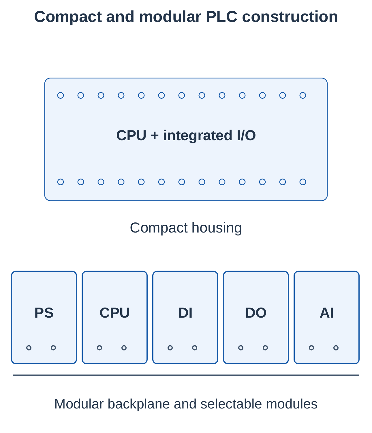
A compact PLC combines its CPU, power arrangement and a defined set of I/O in one housing. Many permit some expansion. It suits a known, relatively limited signal requirement.
2.17.2 Modular PLC
A modular PLC permits selection of CPU, I/O, communication and special-purpose modules connected through a rack or backplane. It offers expansion but requires compatible hardware and configuration.
| Feature | Compact PLC | Modular PLC |
|---|---|---|
| Construction | Integrated housing | Separate compatible modules |
| I/O arrangement | Defined built-in set with supported expansion | Selected according to module and system limits |
| Selection focus | Known signal requirement | Flexibility and expansion |
| Classification Basis | Common Categories |
|---|---|
| Construction | Compact and modular |
| Capacity | Small, medium and large, with vendor-dependent boundaries |
| Architecture | Centralized, distributed and networked |
| Execution platform | Dedicated hardware or suitable software-based platform |
| Special capability | Standard, safety, motion and process-oriented |
2.17.3 Capacity Classification
Capacity depends on I/O, processing, memory, communication and manufacturer range. No universal I/O-number boundary applies to all vendors and generations.
2.17.4 Distributed and Software-Based Arrangements
Distributed I/O extends field connections over a network. A distributed controller places processing near the process. Remote I/O does not necessarily execute an independent program.
A software controller operates on a suitable computing platform. Its execution environment, deterministic behaviour, I/O integration and support matter; an arbitrary desktop program is not automatically an industrial PLC.
2.17.5 Specialized Controllers
Safety-capable and motion-oriented controllers provide specified functions within suitable systems. A safety PLC still needs correct sensors, outputs, application design and validation.
2.18 Developments in PLC Systems
PLC systems combine local control with diagnostics, engineering tools and plant information. The capabilities described here depend on the product and configuration.
2.18.1 Networking and Distributed I/O
Networks reduce some point-to-point wiring and provide device information. They require addressing, configuration, suitable cabling and defined behaviour during communication failure.
2.18.2 Integrated Capabilities
Controller families may support analog regulation, motion coordination and diagnostics alongside discrete logic. Some combine control, visualization and computing functions. Select capabilities against requirements rather than assuming every PLC includes them.
2.18.3 Engineering and Commissioning
Reusable program structures, simulation and virtual commissioning support sequence testing. Simulation quality depends on its process model and assumptions, and does not remove the need for relevant equipment verification.
2.18.4 Data and Cybersecurity
Controller information supports maintenance, quality and production analysis. Controlled access, backups, network separation and managed changes support dependable operation. A network connection alone does not establish reliable or secure information.
2.18.5 Relay Logic Versus PLC Logic
| Feature | Relay Logic | PLC Logic |
|---|---|---|
| Logic changes | Often requires rewiring | Program modification |
| Physical logic contacts | Many physical contacts | Fewer physical logic contacts |
| Complex decisions | Wiring grows rapidly | Software can scale more readily |
| Diagnostics | Trace wires and contacts | Status and diagnostic tools |
| Power switching | Still required | Still required |
| Failure behaviour | Depends on circuit | Depends on system and configuration |
2.18.6 Selection Example
A simple independent switching task may be economical with relays. Numerous linked sequences, frequent changes and diagnostic needs may favour a PLC. Mixed systems commonly use PLC logic with relays and contactors for interfaces and power switching.
2.19 Quick Revision and Exam Practice
2.19.1 Essential Ideas
- Define the unoperated state before interpreting NO and NC contacts.
- A relay coil operates its associated contacts.
- Series paths implement AND; parallel paths implement OR.
- An NC contact can implement NOT of the associated relay’s operated state.
- Holding contacts provide memory through feedback.
- Stop and trip must interrupt all coil-maintaining paths.
- Contactors switch suitable loads but do not replace protection.
- DOL starting applies rated line voltage directly.
- PLCs replace much logic wiring with stored-program decisions.
- Construction, architecture and specialization are different classification bases.
2.19.2 Important Relationships
| Relationship | Use |
|---|---|
| K = A · B | Series AND contacts |
| K = A + B | Parallel OR contacts |
| K(next) = P · [S + K(previous)] | Stop-permitted holding logic |
| I = P ÷ V | Illustrative steady DC-coil current |
| Starting current = Stated factor × Rated current | Motor-current example with a supplied multiplier |
2.19.3 Numerical and Reasoning Practice
Question 1: DC-Coil Current
A 24 V DC coil is rated 4.8 W. Find nominal steady current.
Answer: I = 4.8 ÷ 24 = 0.20 A, under the stated model.
Question 2: Starting Current
A motor’s rated current is 12 A, with assumed starting factor 5.
Answer: Starting current = 5 × 12 = 60 A. The multiplier is an example input.
Question 3: Combined Logic
For K = (A + B) · C, evaluate A = 1, B = 0, C = 0.
Answer: (1 + 0) · 0 = 0 because the common permission C is absent.
Question 4: Holding State
For P = 1, S = 0, previous K = 1, find the next state.
Answer: K(next) = 1 · [0 + 1] = 1. If P becomes 0, K(next) becomes 0 regardless of start.
Question 5: Tank Restart
After supply restoration, level is between the thresholds, L is open and K has released. What happens?
Answer: K remains off in the illustrated holding circuit until the low-level request closes.
2.19.4 Long-Answer Examination Questions
- Draw and explain electromagnetic relay construction and operation.
- Explain NO, NC, changeover, pole and throw with diagrams.
- Classify relays and compare electromagnetic and solid-state operation.
- Implement AND, OR and combined logic using relay contacts.
- Explain relay memory using a start–stop holding circuit.
- Explain contactor construction and its advantages for motor switching.
- Draw DOL power and control circuits and explain start, stop and overload operation.
- Solve a tank-filling or permissive-conveyor relay problem.
- Explain PLC development, capabilities and the basic block diagram.
- Classify PLCs and compare compact and modular construction.
2.19.5 Short-Answer Practice
- Why is the holding contact parallel to start rather than stop?
- Does a contactor auxiliary contact prove motor rotation?
- Why does an overload relay not provide complete short-circuit protection?
- How does a maintained automatic request affect restart behaviour?
- Why can PLC-controlled systems still need relays and contactors?
Unit 2 recall: Coil → Contacts → Logic → Memory → Contactor → DOL → PLC. Trace a complete path, update contacts and check stop, trip, power-loss and recovery behaviour.